Join Our Ford Truck Forum Today

Document your Ford truck project here and inspire others! Login/Register to view the site with fewer ads.

How to test a PIP Sensor.

I have been asked many times how to test a PIP Sensor by itself so here is what I came up with.

Playing at the bench this weekend with a Distributor and PIP Sensor and here is what I found out about testing a PIP Sensor.

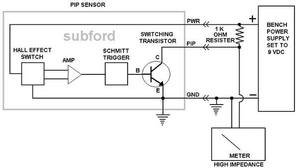
The PIP Sensor just has an off and on output but to test it you have to put voltage on the PIP at the plug through a voltage-dropping resistor.

I hooked it up like the diagram below and turned the distributor slowly by hand.
The meter went to full voltage and dropped back to zero as I turned the distributor.

I did not have a TFI (ICM) module hooked to it during the tests as I wanted to come up with a test to find out if it was the PIP or the TFI that was bad.

This would work to test the PIP Sensor if you had no spark. But if it quit while the engine is warm then you could put a hair dryer on the PIP and crank the engine to test it.

You can also use the 12 Volt Battery in the truck for this test but I was thinking about a 9V battery and a LED at the time I did the test.

Ford truck enthusiast forum - FTF

/
 
Last edited:

Old_Paint

Old guy with old cars
225
29
Alabama
Ahhh, feels like home now. Sub's put up a diagram.

And a nifty diagram it is. Nice work. But why 9V? Is that what the source voltage normally is to the PIP in the vehicle? Not challenging, just asking.

And now, for your viewing pleasure, a diagram showing a rig for TFI testing. (Please?)

This definitely belongs in a tech article.
 
I was thinking about a making a PIP tester with a small 9V battery and an LED so that is why I was using 9 Volts to see if it would work with 9 Volts. It normally gets battery voltage from the key and I think the TFI module has the resister in it for the PIP wire.

On the remote mounted TFI (ICM) I think the PIP resister is still in the TFI module but do not have one to test on the bench find out.

I tried to edit the diagram above but lost it so I had to repost it here.

PIP_sensor.jpg


/
 
Last edited:

Old_Paint

Old guy with old cars
225
29
Alabama
Hmm, open collector output, and I don't think the PIP module has changed since relocating the TFI from the dizzy to the fender, but I could be wrong, so maybe the Ford experts present can chime in. Being 12V, the PIP signal will be fairly resistant to noise, but I do recall some shielding on the 3 conductors running from the dizzy to the TFI on my '92. I guess we could find out by checking with an ohmmeter from the PWR to PIP at the dizzy, then look back the other way at the TFI. Should be open circuit if the sensor is truly Open Collector. Any idea what value that resistor should be?

What would be REALLY cool, would be a tester that will trigger the TFI with a spark tester on the coil. That would require an oscillator in addition to the LED, to simulate the output of the PIP and fire the coil. A frequency of 53 Hz would be perfect to simulate 800 RPM idle speed on the 8 cylinder. But wouldn't really matter the frequency as long as it isn't TOO fast (6000 RPM/60 sec * 8 PPR / 2 revs/cycle = 400Hz), and the spark gap tester was in place. Gotta be a good square wave, tho, which actually gives two sparks per pulse (one going up, one coming down).

Worst case, high impedance output to send the pulse over to the TFI. It needs to be at least 10X the input impedance of the TFI. The only purpose of that resistor is to limite the current through the transistor used for the output. Now, if it just had clips on it to connect to the battery .... Test everything in place with no invasive work. Problem would be testing one with a dizzy mounted TFI. Perhaps a gutted TFI module with a plug hanging out of it like the one on the PIP for the remote mounted units. I've seen this done on Fox Body T-Birds to get the TFI away from the radiator heat. That would require sacrificing a PIP and a TFI to build an adapter, but who says either has to be a working unit to get the TFI case or the PIP harness?

If you build it, they will come. This has good potential, Bill. Imagine proving the PIP, TFI, and coil are all good without removing a single part from the engine bay? Or, having a tool to verify a dizzy rebuild is good BEFORE you've re-stabbed the dizzy? Or a tool to find out if the TFI is having thermal breakdown syndrome? I like it, a lot.
 
I took a remote mounted TFI (ICM) and put power on the power pin and I got zero volts on the PIP pin. So the power does not come from the TFI module and the resister is not in the TFI module.

I hooked my BOB to my mock 89 van EEC-IV set up and checked the PIP pin at the BOB as I turned the Distributor by hand and it went from zero volts to 12 volts as I turned it. The Distributor was mounted in my Distributor Tester and the Ignition Coil did fire the spark tester as I turned it.

So I have concluded that the voltage for the PIP pin comes from and supplied by the PCM.
 
Last edited:
I took a remote mounted TFI (ICM) and put power on the power pin and I got zero volts on the PIP pin. So the power does not come from the TFI module and the resister is not in the TFI module.
Wrong, I was on the wrong wire. Sorry about that.
So I have concluded that the voltage for the PIP pin comes from and supplied by the PCM.
Wrong, It comes from the TFI Module.
Any idea what value that resistor should be?
Information from the web says 1200 Ohms but when I measure it I get 1.135K Ohms.
And a nifty diagram it is. Nice work. But why 9V? Is that what the source voltage normally is to the PIP in the vehicle?
The voltage at the PIP Power PIN is 11.55 Volts with 12.0 Volts on the Run Power Pin of the Module.
PIP signal out is 0.0 - 11.43 Volts with the 12.0 VDC on the Run Power Pin of the Module.
 
Last edited:

Old_Paint

Old guy with old cars
225
29
Alabama
Ok, good info there. The 1200 vs 1135 is probably just the tolerance of the resistor (my guess would be a +/-5% resistor because they're cheaper), as well as the calibration of the meter and impedance of the leads/contact points. 5% of 1200 would be 60 ohms, which puts you VERY close to the 1135 that you measured. Tighter tolerance resistors tend to be more subject to drift caused by heating. Let's face it, it gets HOT under the hood. 11.55 sounds like a good diode drop of 0.3 - 0.7 V, depending on the breed of diode. Likewise for the 11.43. Again, throw in the calibration of the meter. It could be off a few millivolts, and still be plenty accurate enough for automotive work. Typicially in automotive work, we're not worried about anything much less than .05V (50 mV) error.

The power output to the PIP from the TFI may possibly be protected from back-bias with a diode of some sort. Common practice with power supply outputs, plus, if you get stray spark inside the dizzy hitting the PIP, that's some enormous voltage going back into the TFI. This would probably be a bad thing. Unplugged, it should read the full 12V, unless there is a burden resistor AFTER the diode, but still in the TFI. Again, common practice for better voltage regulation, but rather than a diode, it may just actually use a simple resistor network to limit current to the PIP power in case the PIP sensor fails shorted. That would prevent damage to the TFI electronics from overcurrent, but not from overvoltage.

The open collector voltage will be slightly lower than the Vsupply, but not much since it uses Vsupply across the resistor to produce the pulse. That output would also be dependent on the biasing of the base on the transistor, which again will be dependent on the tolerances of other electronics inside the PIP. The PIP output goes high when the transistor turns OFF, and low when it turns ON. Open collector logic requires thinking backward, but tends to be more robust and reliable than open emitter. The 1.2K reisistance is purely to limit current through the output transistor. So, at 12V/1200 Ohm, that would be 1 mA current through the PIP to turn off the output by essentially tieing the collector to common. About 1.2 mW dissipation, and about the same to trigger the TFI when the transistor turns off.

So, after all the electronics analyzing, what ever one uses to drive a TFI needs at least 1 mA capacity and have a nice square wave with a relatively short duty cycle. That's another thing that's going to matter, but maybe not as much as I think. Most any off the shelf oscillator from Radio Shack can handle what is needed. It's just a matter of choosing one with a low enough frequency band, or doing some frequency dividing. With your testing, I can now theorize that the sooper dooper "double spark" ignition systems don't do anything more than a standard Ford TFI, unless those systems change the vane to a slotted vane, or unless they're doubling the pulse from the PIP somehow. Possible, but I'd have to see the output with a scope to believe it. When the TFI is gated ON, it interrupts the ground to the coil, bang, we got spark. When it turns back off, again, bang we got spark, so two spark pulses (leading edge and trailing edge) for each vane passing the PIP. It may be the second pulse actually happens before the arc from the first extinguishes, in which case, it looks more like an extended spark.

Next time you're playing at your workbench, turn the dizzy VERY slowly, and see if the spark tester doesn't fire twice, once as the vane passes in front of the PIP, and again as it clears the PIP. If you watch the voltage at the primary (12V side) of the coil with a scope, you'll see it actually 'rings', and can be a very considerable voltage spike. This is where LRC tuning comes in, to amplify a stepped pulse with resonance. I verified this with my senior design project in 1982 when I built a digital tachometer for my VW. I did it with all discrete components, and the FIRST thing I did was FRY some CMOS parts the first time I connected it to the coil. I'd done all the testing and design using a sweet function generator, that was very gentle on the input stages. Little did I know that I would be getting 120V P-P pulses out of a 12V circuit. So, back to the drawing board to build an input stage that was a bit more robust.

Now, for even better bench testing, wouldn't it be really neat to be able to circulate hot water through a heat-sink to raise it to normal engine compartment temperatures, to see if the TFI breaking down when it's hot? This is the ONE thing the nifty difty testers at auto parts places DON'T check, and also the very problem that made Ford relocate the dizzy mounted units to a FAT heat sink AWAY from the engine and radiator.
 

Bob Ayers

North Carolina Chapter member
1,474
111
Durham, NC
So, at 12V/1200 Ohm, that would be 1 mA current through the PIP to turn off the output by essentially tieing the collector to common. About 1.2 mW dissipation, and about the same to trigger the TFI when the transistor turns off.

Check your math.....it's actually 10mA


Open collector logic requires thinking backward, but tends to be more robust and reliable than open emitter.

The voltage swing with open emitter will be the voltage applied to the base (say 12V) - the Tx Vbe (say 700mV). so the output swing will be roughly 11.3V, but it will be in phase with the base signal. Other than a slightly reduced amplitude (taking the Vce(sat) into account), open emitter (also called emitter follower) should be just as reliable as open collector. And since the transistor will not go into saturation
(like the open collector), emitter follower circuits are usually faster than
common emitter (open collector) circuits.
 
Last edited:

Bob Ayers

North Carolina Chapter member
1,474
111
Durham, NC
I did was FRY some CMOS parts the first time I connected it to the coil.


All CMOS chips (with the exception of SOI) have a characteristic called LATCHUP. This is due to the parasitic bipolar devices in the CMOS PFET/NFET structure. These parasitic bipolar devices create an SCR, VDD = ANODE, GND = CATHODE, and the chip I/O's = GATES. There are process techniques (diffusion guardrings, etc.) to minimize the current gain (Hfe) of these parasitic bipolar devices, but cannot be eliminated.

This is from a class I developed several years ago:


256780989_4XSvZ-X2.jpg


smiliehijacked smiliehijacked smiliehijacked smiliehijacked
 
Last edited:

F 150Cobra

"Wild HoRsE" Got Torque?
3,642
104
Aruba
was is the sympton of a bad PIP sensor?
 
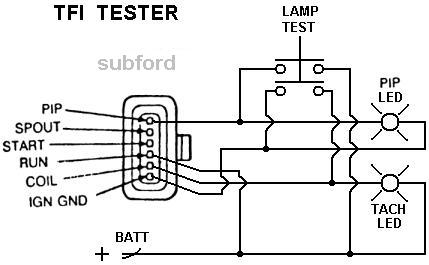
Old Paint how about this for a PIP and TFI tester?

If the PIP is working the PIP LED will flash while cranking.
If the TFI is working the TECH LED will flash while cranking.

TFI_Tester_Diagram.jpg


/
 

Bob Ayers

North Carolina Chapter member
1,474
111
Durham, NC
Old Paint how about this for a PIP and TFI tester?

If the PIP is working the PIP LED will flash while cranking.
If the TFI is working the TECH LED will flash while cranking.

TFI_Tester_Diagram.jpg


/


Looks good Bill! The only problem I see, if you push the "lamp check" switch while cranking, you will blow the PIP.
 

Old_Paint

Old guy with old cars
225
29
Alabama
I like it. I like it a lot. But, you show one LED connected to BATT, and the other connected to IGN GND. Is that to NOT the NOT logic of the open collector of the PIP? Now, do we know what the SPOUT signal is? Is that a pulse train, or just an analog signal to phase shift the COIL signal for timing advance?

The only reason I suggested an external oscillator for checking the TFI, was so that it could be tested without even having it on a dizzy, or more particularly, without anything rotating. Safer for the fingers and all.

Oh yeah, seems I did dip a sligit with the math. Too big a hurry and too absorbed in the concept, I guess.
 
But, you show one LED connected to BATT, and the other connected to IGN GND. Is that to NOT the NOT logic of the open collector of the PIP? .
I do not understand what you are saying or getting at.
Now, do we know what the SPOUT signal is? Is that a pulse train, or just an analog signal to phase shift the COIL signal for timing advance? .
The SPOUT is an input from the EEC Computer and yes it is a pulse train to phase shift the COIL signal for timing advance
The only reason I suggested an external oscillator for checking the TFI, was so that it could be tested without even having it on a dizzy, or more particularly, without anything rotating. Safer for the fingers and all.
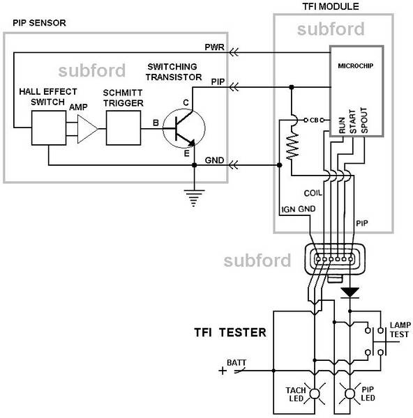
This tester is to test the TFI & the PIP Sensor without removing the Distributor and to tell you the bad item.

An external oscillator could check the rest of the Ignition system and to generate spark while the TFI Module and SPOUT (Computer) are unhooked from the Ignition system.
That’s next.

Tester_TFI-PIP.jpg


/
 

Old_Paint

Old guy with old cars
225
29
Alabama
Gotcha.

I was just trying to figure out why one LED is connected from PIP to GND, and the other is from COIL to +12V. It dawned on me after I looked at it again. DUH. The coil output switches the GROUND side of the coil, doesn't it (also open collector). Momentary lapse of reason. Nevermind. I still like it. Good little box to have, even on the side of the highway while the TFI is hot, and possibly not working. One little fuse to protect it, and bingo, it's done.

I've never studied the SPOUT from the ECM, for that matter the internals of the TFI. Never had one fail, actually. Still got the original on my '86 Bird. But, now that I've said THAT .....

I'm old and slow, but I get there.
 

Old_Paint

Old guy with old cars
225
29
Alabama
Bill,

I think too much sometimes. Wouldn't it be a good idea to know how much current the TFI is actually switching through the coil too? The LED will let you know if the TFI is switching, but not if it will continue to switch under full burden. Would it be better to put some resistance in the Coil output circuit, then just hang the LED across that? Dunno if the DC resistance of the coil would be the right number, though, because this is no longer DC impedance we're talking about with the current through the coil being switched. The equation V=L dI dt comes to mind here for the reactive component of the coil. The coil is actually a tuned RL circuit. Throw in the condenser (capacitor) for more tuning for resonance. Our trucks will run without the condenser, or so I've read, albeit I'm not sure how well. Older breaker points ignition systems won't, well, not for very long. Too much arcing across the points without the condenser will erode the contacts, as well as really screw with the dwell. It may only be there for noise supression on TFI systems, though.

That's going to be a pretty hefty output. Thermal breakdown would be due to a combination of the current for the coil, as well as engine/radiator heat. Yes? There's got to be a reason for the huge heat sink on remote mounted units, otherwise, they'd just be mounted to the sheet metal. I don't think it was just so they could use the same silly tool and screws to mount them. This would also explain the continued requirement for heatsink compound under the TFI.

This could be a hard measurement to get, considering the trashy wave form at the coil caused by the RLC circuit resonance. Got any specs I don't know about? You scare me sometimes with some of the info you come up with.
 

Bob Ayers

North Carolina Chapter member
1,474
111
Durham, NC
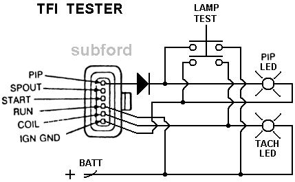
How about this then?

TFI_Tester2.jpg


/


Much better Bill! The diode will block the 12V from feeding back into the PIP collector when you push the lamp chk switch.

With regards to the TIF (TACH) LED, you can get some large voltage spikes on the coil terminal that will probably blow the LED.
 

Ford Truck Articles

Recent Forum Posts

Top