Join Our Ford Truck Forum Today

Document your Ford truck project here and inspire others! Login/Register to view the site with fewer ads.

Cruise Installation in a 1970 F-100

First post here. Sorry if this is the wrong section.

I'm trying to put together a list of parts needed to convert the 1970 F-100 Flareside I'm rebuilding to accommodate cruise control. Since many of the parts will likely be Generation 6 & 7 I've opted to post here.

It looks like there are several here that are very knowledgeable on the subject.

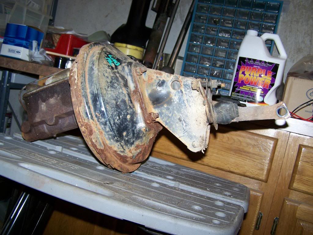
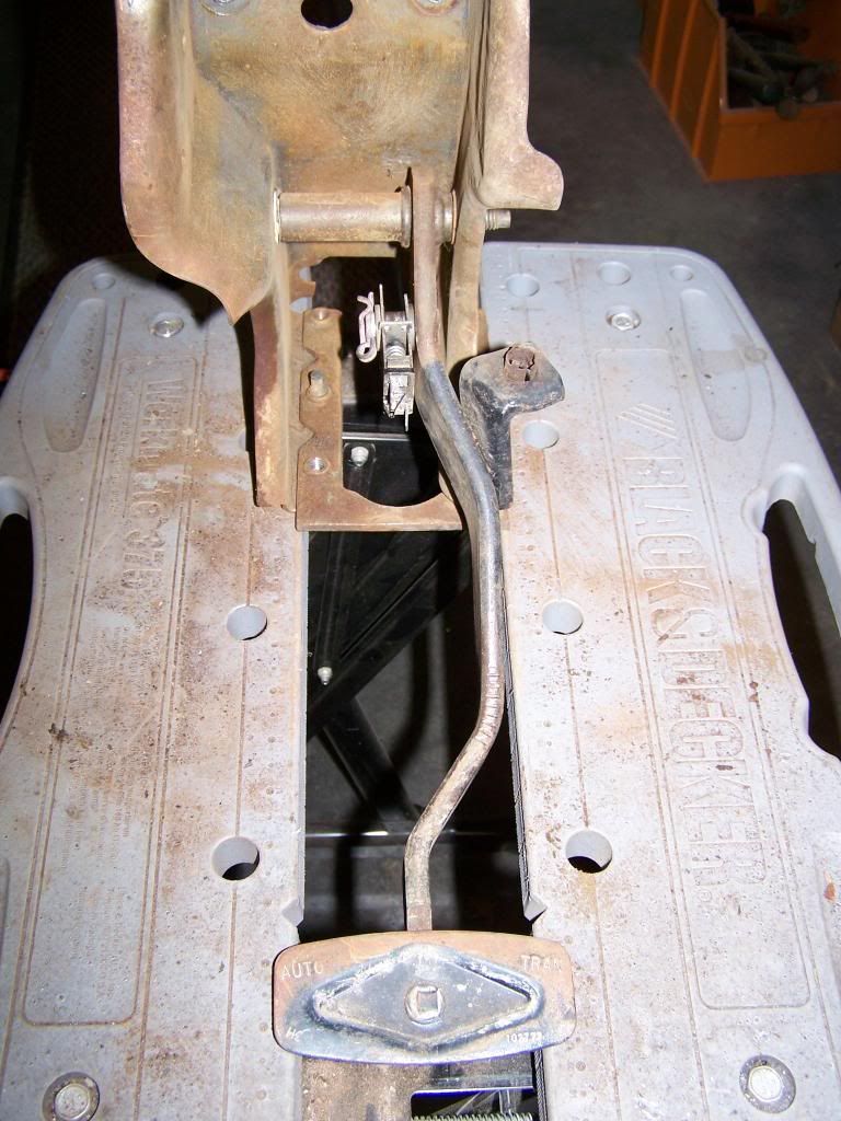
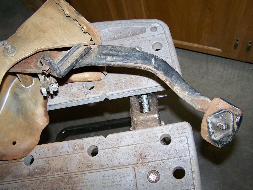
I've converted my truck to a power steering disk brake front end by swapping in a 1976 Disc Brake suspension. I've picked up, what I believe would be a suitable brake pedal for the cruise control D7TZ-2455-D suffix MA, but I'm not entirely sure which brake booster to pair it with. Can someone help?

Pete
 

Mil1ion

Still Da Man
This list is quite complex and not easy to find.

Rule out anything from 77 on.

Look for a system from the 73-76 trucks

I have exploded diagrams.
I have a list of boosters and what they apply to.
This will be a long thread.
 
Dennis,

The brake pedal indicated above would be for a 1977 truck. I picked it up because the Fordification site indicated it could be modified to fit by grinding the pivot end down from the 1977's 3-1/8" to the 1970's 2-7/8". See: http://www.fordification.com/tech/clutch-brake-brackets.htm

I also see from reading the information from that site that I must use the 1977 booster. But it doesn't go into greater detail about how to identify the correct one, i.e., part number, push rod length and number, bracket details, etc. Thus I was hoping to get some help from you great guys here.

Also, I have a 1978-79 steering column and a 1980-86 steering wheel with the cruise control features. I'll be adapting the wheel to the column. And then using the 1980-84 wire harness, amplifier, actuator and servo, and vacuum metering valve. This should give me the extra feature of the vacuum disconnect that I believe was missing from the 1979 and earlier trucks.

Once I get past these hurdles, I'll need to fabricate a bracket for the carburetor - I have a modified 300, 6-cylinder with a Holley 390 4-barrel. And behind it I have a modified AOD transmission.

I realize that these modifications won't make life easy for adapting the cruise control, but I don't mind a little tinkering until I can get things to work. I appreciate any insight you can provide and realize you are talking about "stock" applications and I'm on my own (risk) when it comes to customizing :headbang:

Pete
 

Mil1ion

Still Da Man
The 78-79 column will cause More alterations because of the NSs/bu switch because it is located on the transmission.. now you have to add a transmission that won't work on an FE engine
The brake pedal could fit one of 3 different applications, the booster and pedal have to match the pedal assembly.
In 1979 from DJ0001 the booster made a dramatic change and has a different mounting system.

Now you're dealing with firewall changes with a 79.

I have what you want in my 1977.
77 steering column and 78-79 steering wheel ..w/o a functioning NSS/BU switch.
I still have rtto suggest an earlier version of speed control

I can post a list of speed control parts required to show you.
The engine attached parts are specific to engine.
Speedo cable the same
The pedal assembly will be different. As well as the pedal and booster. 1977 pedal has MA stamped on it.
Special booster and pedal for speed control.
The wiring is easy and with the 80's version gets you the Resume option.

The main obstacle is the mechanical from master cylinder to the design of the brake pedal.
After that your choice of column causes more grief because of how the nss/bu switch works


Last edited:
NSS/BU switch

My engine/transmission combination is the 300 cu. in. 6-cylinder with the AOD. I don't have an FE engine. And there are no fancy electronics in an AOD other than switches.

On an AOD the NSS/BU switch is mounted on the transmission above the range selector lever. To wire it into the harness, we simply need the pin-out of the switch. Courtesy of http://www.lentechautomatics.com/aodtech.html
Click on installation manual and go to page 23 (or 17 in Adobe) for pin out.

There are four terminals on the switch. With the key in the 12-o-clock position and moving counter-clockwise we have terminals 1, 2, 3 and 4. (Note: harness rotation would be clockwise). Terminals 1 & 2 work the backup lights. Terminals 3 & 4 work the neutral safety switch.
Terminals 3 & 4 are both red/lt. blue and wire between the ignition switch start pin and the starter relay. Terminal 1 is black/pink and ties into the backup lights. Terminal 2 is purple/orange and ties into the signal flasher by way of fuse #5.

Steering Column and Wheel

The steering column I have happens to be a 1978-79. As you say, I could also use a 1975-77, however the earlier column has a different turn signal/hazard switch - which means that you can only use 1975-77 steering wheels with it (and cruise control ones are hard to come by).

The 1978-79 column will readily take a 1978-79 steering wheel. But a 1980-86 wheel can also be adapted. The 78-79 column has splines all the way around the shaft, while the 80-86 has a 5/16" flat spot in the splines. To adapt the wheel, simply file-out the flat spot so it will slip over the earlier shaft. 1978-86 have different cruise buttons than the 1975-77. And there's also the added benefit of the vacuum dump pedal switch on the later models.

Brake Pedal and Booster

The brake pedal is somewhat unique because it must accommodate the different brake light switch required of the cruise control. As you say, there were three choices for the 1975-79 period.

To fit the brake pedal into a bumpside, the pivot shaft must be ground down from its original dimension of 3-1/8" to 2-7/8"
The brake pedal must then be mated with a correspondingly different booster. Thanks for the illustrations for the push rod identification!! :wavey:

I believe those part numbers would yield the combinations in the following table.

However, the brake booster also presents an additional problem for the bumpside - the booster bracket and/or the push rod. Fordification says the bracket changed sometime in the later years. Instead of parallel angles front and rear, they had divergent angles. This, and possible changes in the push rod means that they cannot be mounted on the bumpside firewall and dash without MAJOR modifications that I don't want to get into. Fordification says that this change in bracket geometry occurred between the 1977 and 1978 models. Everything from 1977 and earlier being okay for the bumpside.

My confusion, and question then, is confirmation of the date of the change and which parts were affected. Option #4 is out of the question. But Option #3 in the table says that these combination of parts are good from 1977-79, while Fordification says don't use anything from 1978-79. Therefore there's a one year overlap (1977) that I'm unclear about. Can I use Option #3 because the booster bracket will be okay, or will this booster bracket and/or push rod present problems with its attachment to the firewall?
 
Last edited:
is what your doing here have to look stock??

Because the CC out of a 89 to 93 Fox body Mustang would work on that truck. If you could speed sensor to work in your trans. or find the OEM inline Sensor. the one that goes in the speedo cable.
 

Mil1ion

Still Da Man
The 78/79 with speed control and adjustable column TS switch is the most rare TS to find.


he booster and fulcrum style bracket changed in 1979 post DJ0001

Everything after that is different.
You need the booster and pedal that relates to speed control to avoid more projects.

I have photos of both designs.

Btw, I wasn't aware of engine trans combo because you didn't post it.
I assumed it was a 352.
Now that I know the combo, I change my interest in the parts needed.

What I find is lots of people just have the idea..whereas you have more than that

I am only here to help when needed.
As with a lot of things it always takes a few posts to get all the info out.


Brake switch for speed control.


This switch has two purposes
1) brake light switch for non-speed control
2) speed control shut down switch


Please bear with me as I have never done this swap or install with a pre-73 truck.
 
Last edited:
A later model Mustang cruise control will not work for my needs. Besides being committed in some of the parts I've been purchasing, I doubt the actual feasibility of the swap - without MAJOR modifications.

I did mention the engine and transmission combination in post #3 above. But it may have been rather obscure and you might have overlooked it. Sorry.

I'm sure I'll be needing some help with some of the other parts and pieces as I continue to gather them. I appreciate your patience Dennis, as I pick your brain on this.

Right now, I'd like to stay with my original question regarding the brake pedal and booster. Your last post answers that question, and opens up three possible combinations, as listed on the table I posted: Options 1-3. This list consists of 2 possible brake pedals and 3 possible boosters. I wonder if you might explain the differences between the pedals and boosters contained there so I can understand them better? I'm sure there must be physical differences between a JA pedal and a MA pedal. The same goes for the three boosters. Perhaps you can enlighten me on exactly what they are? The point of understanding the differences is to open up other possibilities in the swap. Sometimes parts can be hard to locate.

For instance, as I wrote above, the 80-86 steering wheels have a flat spot in the splines that prevents them from being installed on a 78-79 column. But with a little filing, the wheel can be modified to work. This opens up more options in choice, while maintaining the functionality of the parts.

If I can understand the brake pedals a little more, perhaps I can do a similar thing with those. For instance, the cruise control pedals differ from their non-cruise counterparts primarily by a nub that is welded to the side of the arm that the brake light switch (that you have pictured above) attaches to. Let's say we locate a non-cruise control pedal D3TA-2455-CA. Perhaps it would be possible to convert this pedal to a cruise control pedal by drilling a hole in the proper location, inserting a clevis pin of the proper length and diameter, and welding it to the pedal arm? I'm far from a numbers-matching concours restoration, but I do want to maintain the safe functionality of parts. Such a modification would be no more difficult than the steering wheel one, but would amount to a safe conversion that would open up more options as I search for parts.
 

Mil1ion

Still Da Man
The pedals have minor but important differences.

There are non-speed control pedals that require a both and nut to attach it to the booster rod.
The speed control pedal has a nub and spring keeper. This design accommodates both the special push rod end hole and the carriage style brake switch.
I had a photo of one posted but it was the post DJ-0001 version.
I can repost it iyw?
There are apparently ( so I'm told) internal booster differences. There is a website that I ask booster questions. It used to be called ....powerbrakerebuilders.com

I'll get back to you on the FT numbers.....going to look for differences.
Problem is my stock of boosters don't apply to you.
Only one does.located in the photo above.
One thing I have noticed is the very end of the rod. I'll post a piuc to show you.

Do you have the JT booster ?
 

Mil1ion

Still Da Man
These two photos relate to the DJ0001 + truck. But they show what rod ends look like and the nub on the pedal.


Mil1ion

Still Da Man
I wish I could see the booster mounting area on the bump side.
Then I can compare the differences or similarities.

The CA pedal is for a non-power brake truck.
 
Last edited:

Mil1ion

Still Da Man
This photo is of your #3 option
Note the end of the rod


Mil1ion

Still Da Man
Attached below is a rather crude drawing I made of what I perceive the CC brake pedal probably looks like, with some letters A-F calling out specific dimensions.

It's my understanding that the overall length of the post-DJ0001 pedal is longer than the pre-DJ0001 pedals due to a change in the pedal housing support. Dimension "C" on pre-DJ0001 pedals is 4" for non-cruise pedals, while this dimension is 2-1/4" on pre DJ0001 non-cruise pedals. These differences, plus the changes in the booster attachments make it unproductive to use this combination (Option #4 on my table).

The dentside pedals differ from the bumpside pedals at dimension "A". Bumpside = 2-7/8" while Dentside = 3-1/8". This I can modify by grinding down this pivot tube to the bumpside dimension.

The non-cruise pedals differing from the cruise pedals with a hole thru the arm at "E" rather than the nub I've drawn. But perhaps I can modify a non-cruise pedal by creating a nub out of a clevis pin or other suitable round piece of steel, and welding it in. In order to do so, and have it work for an appropriate booster, I would need dimensions "C", "D", and "E" - which if I understand correctly must be different between JA and MA pedals (or why would Ford even create two different part numbers). If you or another member can provide some measurements, I have a CA pedal coming that I might experiment with.
 
Last edited:
Back to square one.

I bought a pedal from Green Sales that was advertised as D7TZ-2455-D, but when it arrived it looked nothing like the pedal I needed and had a date code of 8/31/72 on the pedal. So I returned it. :hammer:

Looks like I may have to make due with a modified pedal if I can get some measurements.
 

Mil1ion

Still Da Man
If I find my MA pedal in a reasonable amount of time I will measure it.


Another part you may need is the pedal assembly due to pivot holes for the pedal.
On post #10 You can see two different pivot holes on the assembly.
 
Last edited:
1978BoosterAssembly1_zps7c04b2c8.jpg


1978Housing-Pedal2_zps62220071.jpg


1978Housing-Pedal1_zps1c4ea4e1.jpg
 
Sorry for the picture mix-up. I'm still getting use to photobucket and the posting format here. Let's try this again.

Say, does anyone know where I can get a replacement rubber boot for the push rod & bracket?

1978BoosterAssembly1_zps7c04b2c8.jpg


1978Housing-Pedal1_zps1c4ea4e1.jpg


1978Housing-Pedal2_zps62220071.jpg
 

Ford Truck Articles

Recent Forum Posts

Top