460Trucker
Has the Cat Scratch Fever
Alrighty here we go!
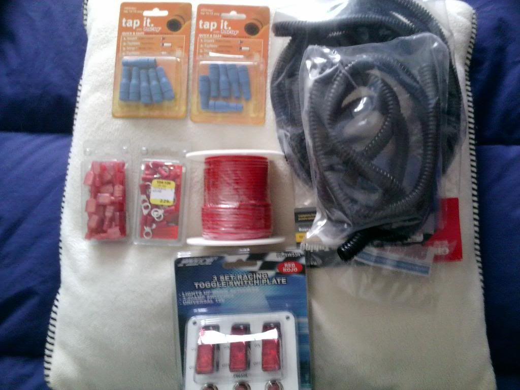
Gather your materials! Here's the list for this specific project (Some items not shown):
- Measuring Tape
- Drill with appropriate bits
- Marker
- Pliers or Crimper
- Wire Strippers
- Appropriate Wire (Today we are using 18 gauge)
- Connectors (Posi-Taps)
- Insulated Female Disconnects (Connects to spades on switches)
- Terminal Rings (Used to establish grounds with screws and bolts)
- Fuse Taps (Used to draw power from fuse slots)
- Switch, mine are rated for 20 amps
- Flex loom/ Tubing
- Silicone gasket maker (black)
- Electrical Tape
- Zip Ties
Determine locations for your switches, power source, and grounds! This is important for determining the amount of wire and flex loom tubing that you need.
IMPORTANT: The model of lights I use are grounded
with a self grounding mechanism. Some require additional ground wiring.
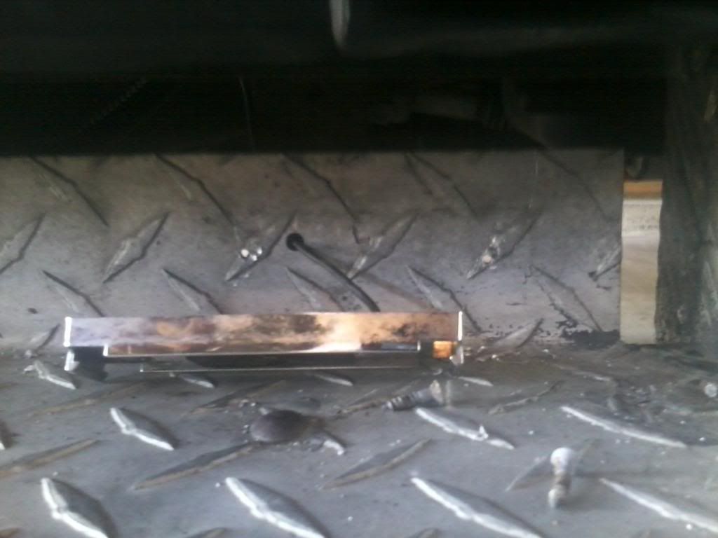
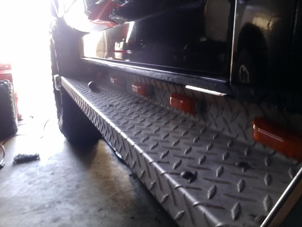
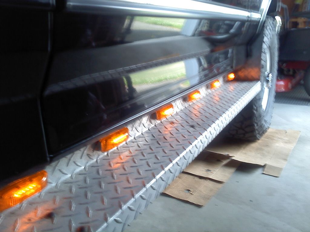
The first step is going to be making your measurements. Based on the number of lights I had bought and the space on my running boards, I decided to mark off an inch on either side for equal spacing.
So measure the length of your mounting surface (running board), subtract 2 inches, and then divide accordingly. I have 6 lights per board, so that means 5 spaces of equal lenghth in between. Divide accordingly
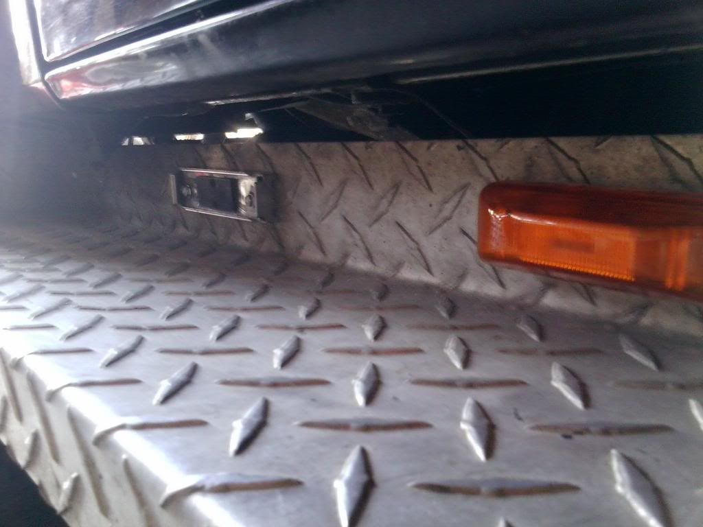
and make clear marks. Now drill out those holes including the one for the wire! Feel free to use your light mounting bracket as a template.
Get those lights on and feed the wires through the holes. To guard against scraping the wire against the drilled out hole you can do a few things: Purchase rubber grommets, seal with silicone, or wrap in electrical
tape or heat shrink tubing. It is personal preference and an extra precaution.
Now determine an approximate length of wire you will need to run from your switch to the furthest light. Here, the furthest light will be the one closest to the front of the truck.
In this case we are using a 3 switch panel so I will start with the first switch on the left.
I like roll the wire from the accessory light to the switch itself so we get an accurate length. Be sure to leave extra to work with. I leave about 1-1.5 inches.
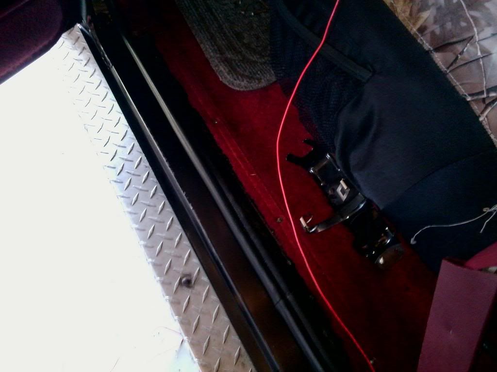
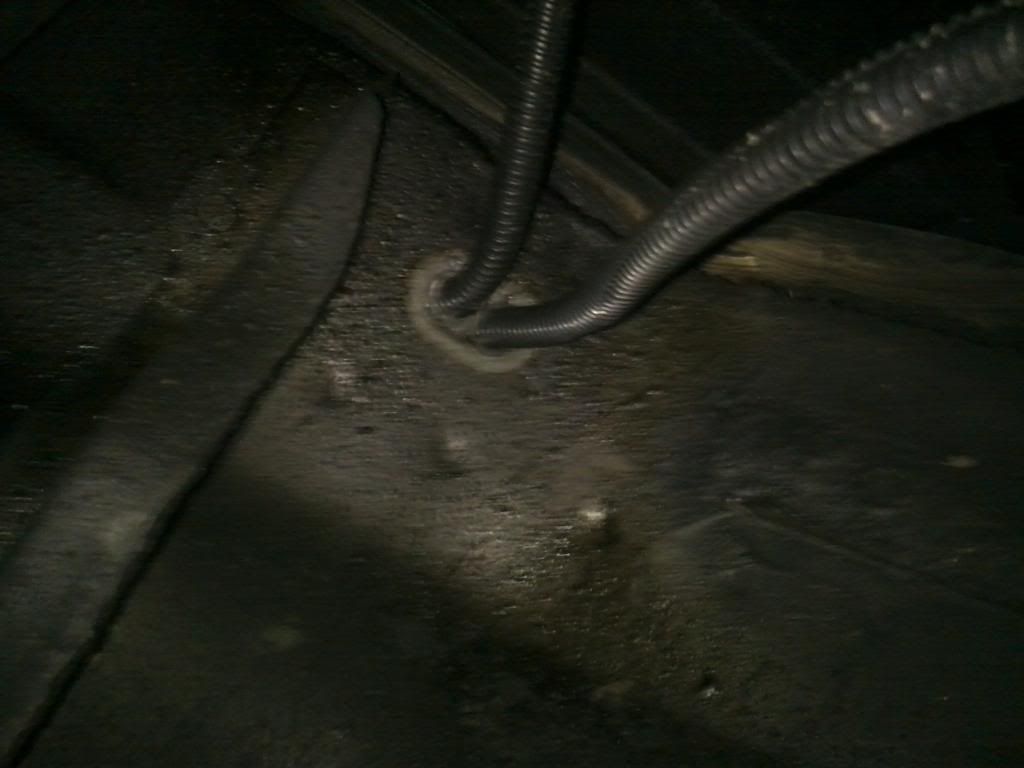
How do we get the wire outside the cab in a clean and professional manner you may ask? There are two holes with grommets on both the driver and passenger side of the cab floor, just behind the seats
(See photos below) Pull the carpet back and you will see the opening hole, feed it through.
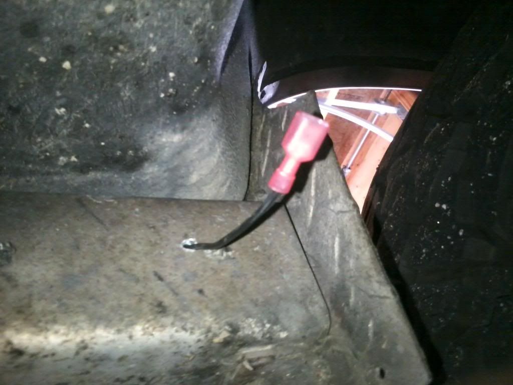
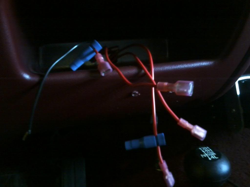
Now time to make the first connection! Strip the end of the wires approximatley 1/4 of an inch. Because it is the first light, we will be splicing without a tap. We have a few options. I will be
using a set of male and female disconnects/connecors with electrical tape. You can also utilize a butt connector.
I don't feel like investing in soldering equipment. You can twist the wire in (or solder it if you choose) and throw some heat shrink wrap on it.
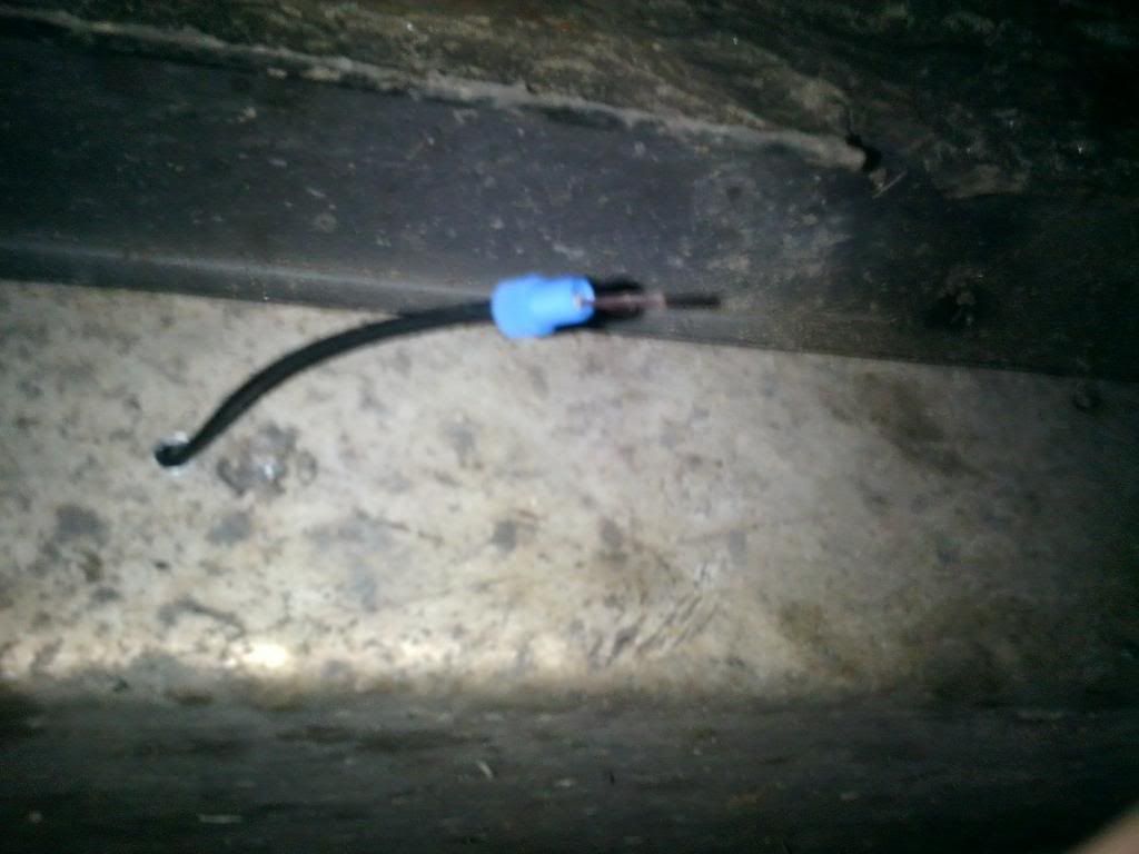
Today we will be using a great product called Posi-Tap for the rest of the lights. They also make straight connectors as well and provide a fantastic seal.
How to use: Unscrew the rear piece, insert the tapping wire through the hole. Screw that back in tight.
Next, unscrew the small piece with the hole, insert the source wire and screw it back on. There ya go! A fantastic and safe connection. I will be wrapping these in electrical tape for extra safety.
One full side of lights is now connected into our power wire! Time to connect it to the switch.
Strip the end of the wire and crimp a female insulated disconnect on the end. Plug that into the power spade on the back of the switch (they should be labeled on the side of the actual switch).
Here's where things will vary. On this particular panel, I have two spades on the back of my switch, some you will see have three spades. One goes to the lights, another to your power source
(Fuse panel is a safe option), and another to the ground. Again, they should be labeled.
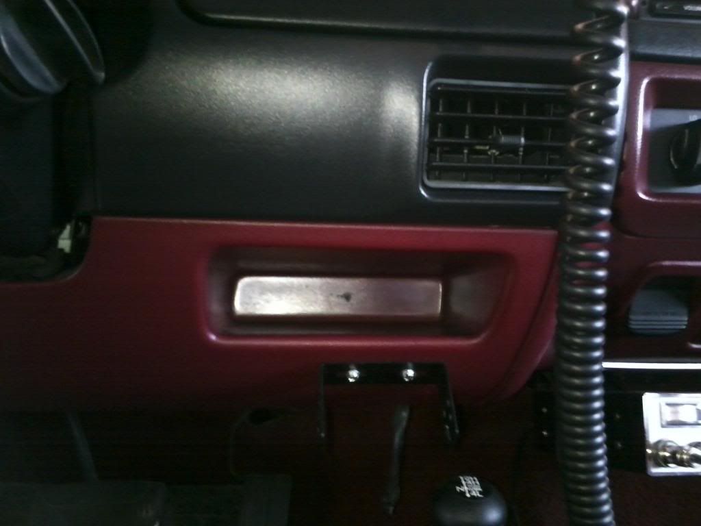
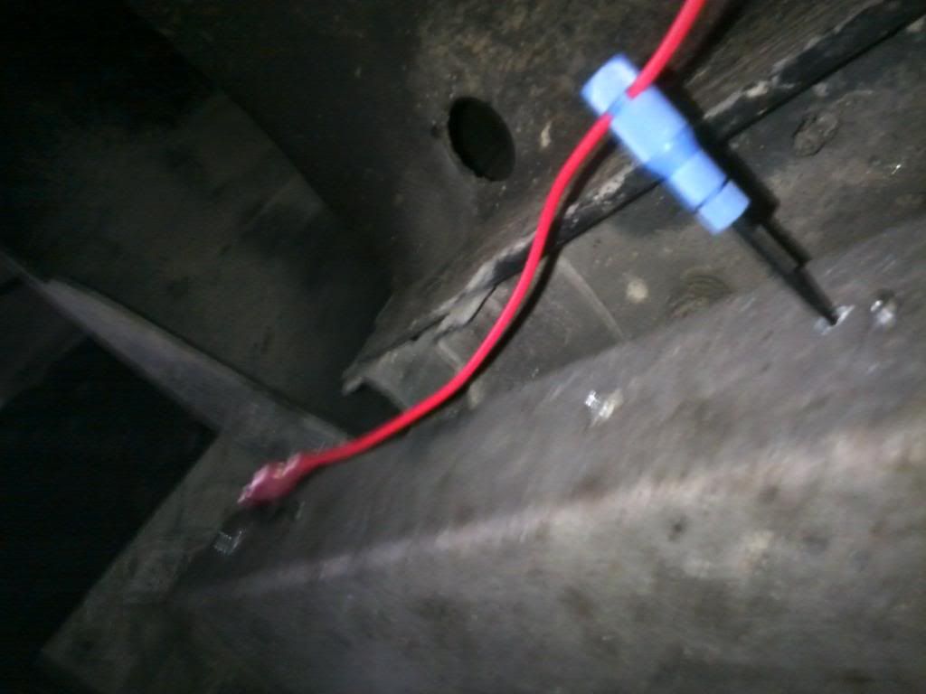
I like to do the grounds second, then the power source wiring. Find a screw or a bolt, measure out your wire, strip the wire ends, attach a disconnect to one and attach to the spade on the switch (or splice into a wire lead,
as I mentioned before it depends on the switch). Crimp a terminal ring to the other end and attach it to a screw under the dash somewhere out of the way. If you have a multi-switch panel like mine, feel free to tap into the other ground wires to save material (Duncan Approved!)
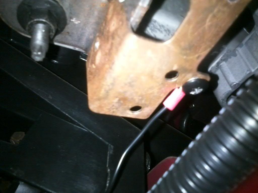
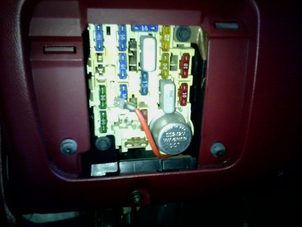
Next, use a thin pair of pliers to pull out a fuse. Preferably a free slot or the one for the dash lights or ciggarette lighter. (BEFORE YOU REACH THIS POINT, ENSURE THAT ALL POWER, GROUND, AND ACCESSORY WIRES ARE PREPARED FOR CONNECTION)
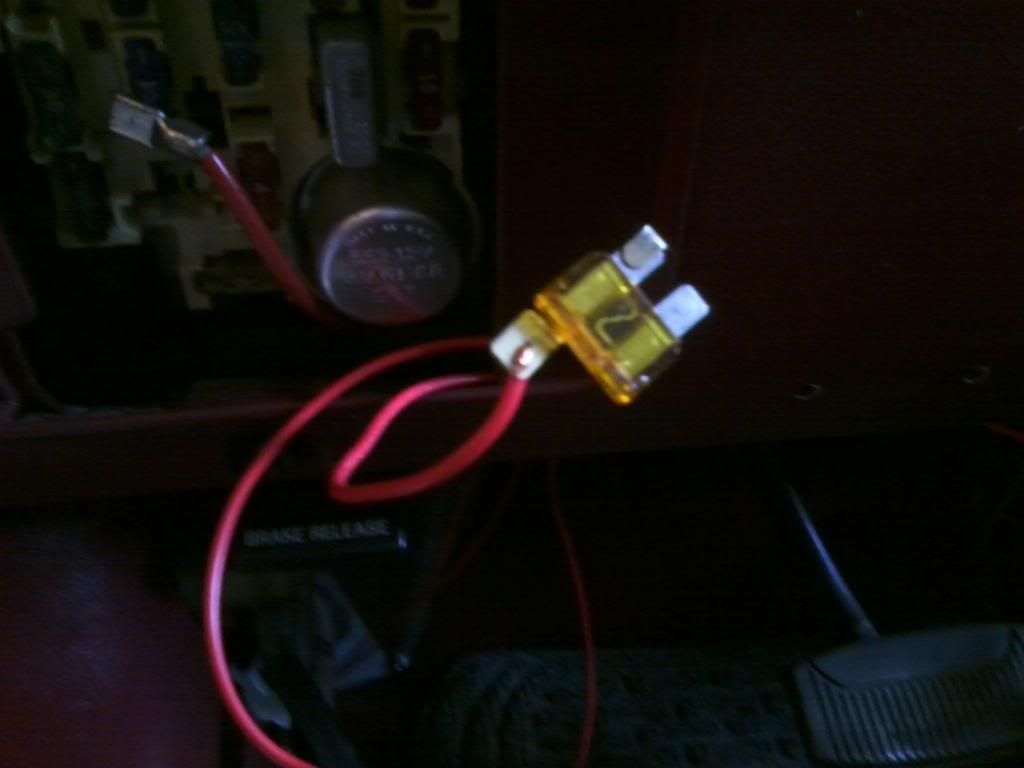
Get your power wire roll back out, lay out a path from the switch to the panel and cut to size just like we have been doing.
Attach a fuse tap to the end of the wire, solder, wrap with tape, or thread it through and cover it depending on the type of tap. It is inside the cab so there are few potential issues for corrosion here.
Crimp another female disconnect to the other end of the wire and plug in to the power source blade on the switch, or splice into the wire lead, in my case it is a plug.
Re-insert the fuse ONLY when you have established a good ground and all your connections are secure.
I waited till every connection I needed to make was made before I began plugging into the back of my switch panel. Depending on the switch you are working with, you may not need to as it is easy enough to deal with just a single switch. After you plug it in, mount the switch and you are good! (Just be sure to connect your power wire last, that way you don't accidentally flip the switch on and not realize you have hot leads.
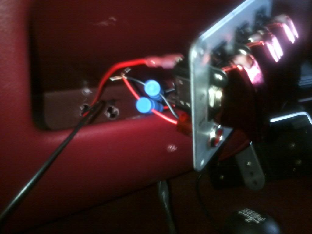
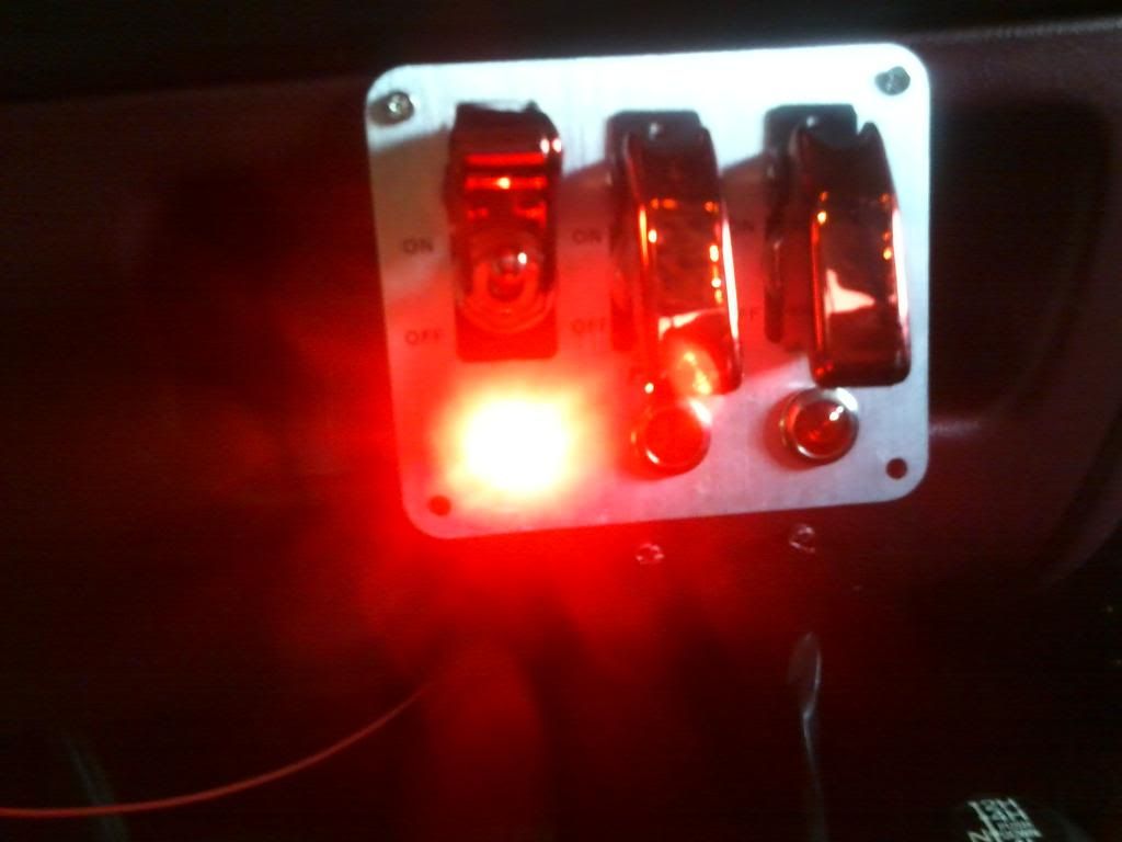
Test out your switch! If it lights up with no sparks or no unecesary heat coming from the switch, you are successful!
Also check each individual light to make sure none are flickering or dim.
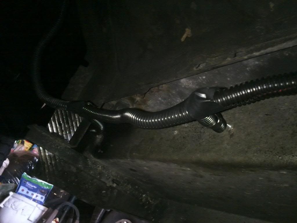
Take your split flex loom, tubing whatever you want to call it and cover
every bit of wire that you can. Use zip ties in places that the wire needs support or where it needs to run across a certain path, like against the back of a running board or at a certain height under the
steering column.
Final note: Some like to draw power from the battery itself. Personally, I do not like that idea for a few reasons. One is that your power source is more exposed to the elements than a fuse box inside the cab.
Second, if you need to change your battery you have to remove the ring terminals from your project.
Now do the other running board and add a ton more lights! Any questions please do not hesitate to ask here or through PM. I'm fine with either.
Gather your materials! Here's the list for this specific project (Some items not shown):
- Measuring Tape
- Drill with appropriate bits
- Marker
- Pliers or Crimper
- Wire Strippers
- Appropriate Wire (Today we are using 18 gauge)
- Connectors (Posi-Taps)
- Insulated Female Disconnects (Connects to spades on switches)
- Terminal Rings (Used to establish grounds with screws and bolts)
- Fuse Taps (Used to draw power from fuse slots)
- Switch, mine are rated for 20 amps
- Flex loom/ Tubing
- Silicone gasket maker (black)
- Electrical Tape
- Zip Ties
Determine locations for your switches, power source, and grounds! This is important for determining the amount of wire and flex loom tubing that you need.
IMPORTANT: The model of lights I use are grounded
with a self grounding mechanism. Some require additional ground wiring.
The first step is going to be making your measurements. Based on the number of lights I had bought and the space on my running boards, I decided to mark off an inch on either side for equal spacing.
So measure the length of your mounting surface (running board), subtract 2 inches, and then divide accordingly. I have 6 lights per board, so that means 5 spaces of equal lenghth in between. Divide accordingly
and make clear marks. Now drill out those holes including the one for the wire! Feel free to use your light mounting bracket as a template.
Get those lights on and feed the wires through the holes. To guard against scraping the wire against the drilled out hole you can do a few things: Purchase rubber grommets, seal with silicone, or wrap in electrical
tape or heat shrink tubing. It is personal preference and an extra precaution.
Now determine an approximate length of wire you will need to run from your switch to the furthest light. Here, the furthest light will be the one closest to the front of the truck.
In this case we are using a 3 switch panel so I will start with the first switch on the left.
I like roll the wire from the accessory light to the switch itself so we get an accurate length. Be sure to leave extra to work with. I leave about 1-1.5 inches.
How do we get the wire outside the cab in a clean and professional manner you may ask? There are two holes with grommets on both the driver and passenger side of the cab floor, just behind the seats
(See photos below) Pull the carpet back and you will see the opening hole, feed it through.
Now time to make the first connection! Strip the end of the wires approximatley 1/4 of an inch. Because it is the first light, we will be splicing without a tap. We have a few options. I will be
using a set of male and female disconnects/connecors with electrical tape. You can also utilize a butt connector.
I don't feel like investing in soldering equipment. You can twist the wire in (or solder it if you choose) and throw some heat shrink wrap on it.
Today we will be using a great product called Posi-Tap for the rest of the lights. They also make straight connectors as well and provide a fantastic seal.
How to use: Unscrew the rear piece, insert the tapping wire through the hole. Screw that back in tight.
Next, unscrew the small piece with the hole, insert the source wire and screw it back on. There ya go! A fantastic and safe connection. I will be wrapping these in electrical tape for extra safety.
One full side of lights is now connected into our power wire! Time to connect it to the switch.
Strip the end of the wire and crimp a female insulated disconnect on the end. Plug that into the power spade on the back of the switch (they should be labeled on the side of the actual switch).
Here's where things will vary. On this particular panel, I have two spades on the back of my switch, some you will see have three spades. One goes to the lights, another to your power source
(Fuse panel is a safe option), and another to the ground. Again, they should be labeled.
I like to do the grounds second, then the power source wiring. Find a screw or a bolt, measure out your wire, strip the wire ends, attach a disconnect to one and attach to the spade on the switch (or splice into a wire lead,
as I mentioned before it depends on the switch). Crimp a terminal ring to the other end and attach it to a screw under the dash somewhere out of the way. If you have a multi-switch panel like mine, feel free to tap into the other ground wires to save material (Duncan Approved!)
Next, use a thin pair of pliers to pull out a fuse. Preferably a free slot or the one for the dash lights or ciggarette lighter. (BEFORE YOU REACH THIS POINT, ENSURE THAT ALL POWER, GROUND, AND ACCESSORY WIRES ARE PREPARED FOR CONNECTION)
Get your power wire roll back out, lay out a path from the switch to the panel and cut to size just like we have been doing.
Attach a fuse tap to the end of the wire, solder, wrap with tape, or thread it through and cover it depending on the type of tap. It is inside the cab so there are few potential issues for corrosion here.
Crimp another female disconnect to the other end of the wire and plug in to the power source blade on the switch, or splice into the wire lead, in my case it is a plug.
Re-insert the fuse ONLY when you have established a good ground and all your connections are secure.
I waited till every connection I needed to make was made before I began plugging into the back of my switch panel. Depending on the switch you are working with, you may not need to as it is easy enough to deal with just a single switch. After you plug it in, mount the switch and you are good! (Just be sure to connect your power wire last, that way you don't accidentally flip the switch on and not realize you have hot leads.
Test out your switch! If it lights up with no sparks or no unecesary heat coming from the switch, you are successful!
Also check each individual light to make sure none are flickering or dim.
Take your split flex loom, tubing whatever you want to call it and cover
every bit of wire that you can. Use zip ties in places that the wire needs support or where it needs to run across a certain path, like against the back of a running board or at a certain height under the
steering column.
Final note: Some like to draw power from the battery itself. Personally, I do not like that idea for a few reasons. One is that your power source is more exposed to the elements than a fuse box inside the cab.
Second, if you need to change your battery you have to remove the ring terminals from your project.
Now do the other running board and add a ton more lights! Any questions please do not hesitate to ask here or through PM. I'm fine with either.
Last edited by a moderator:
")
