Join Our Ford Truck Forum Today

Document your Ford truck project here and inspire others! Login/Register to view the site with fewer ads.

New guy needs vacuum routing for Ca. smog

Thanks Mil1ion. Those will help me. I'm on the way to Ford or aftermarket to track down the VCV location confusion. I need to test some way to see if they open and or close right. Probably end up at the wrecking yard.

I'm good for now. I'll post pics in my gallery and maybe feedback from those will iron out the last few wrinkles.....enough to get past the visual and complete the smog test.

And yes, you are the 'man'.

Cheers,
Dave
 
Complete Carburetor number ?
 
This may help you some as well

VacuumSchematicAbbreviationsFord.jpg
 
Last edited:

BKW

Ford Parts Guru
a VCV (vacuum control valve) thermally actuated usually screws into the T-stat housing
1980 F100 4.9L A/T CA Calibration Codes:

0-52S-R0 (1980/89 Ford Light Truck Parts Catalog, Text, Section 93B = Parts List #12).

0-52S-R0-10 (same as above = Parts List #126).

Both parts lists: E0TZ-12A091-A .. VCV (Motorcraft DY271) / Marked: D8AE-BA

Both parts lists: Carb ID number: E0TE-ALA / Ford part number: E0TZ-9510-AL .. 1V Motorcraft Carburetor (Motorcraft CA2287).

1980 and later: CC parts lists are a necessity, cuz without them, there is no other way to get the part numbers for emissions related jazz.

The parts are not listed separately like they were 1979 and earlier.
 
Last edited:
Yes, those last 2 posts will help. The last one cleared up the DV-TW mystery....delay valve-two way, with a part number no less.

Those 4 numbers on the carb is what the rebuilders are using for verifying the application. The numbers are located on the carb base/driver side. There is a seller of rebuilts on eBay that lists all the numbers that are correct for this engine/year including the numbers on the two I have. I bought a Holley rebuild of the Carter/Motorcraft YFA from Summit and its number fit the application by year. They originally had tags I was told. It would be rare for a tag to survive 30 years I suppose. Could it be that the number on the tag would have been the Ford part number? I would bet on that. The tags probably don't usually survive the first carb rebuild. I have forgotten to put a few back on myself ;-)

The other 3 digit numbers on the carbs are casting numbers I was told.

In any event I feel like I have enough now to piece it together to resemble the original routing.

Again...Thank you sir!

Dave
 
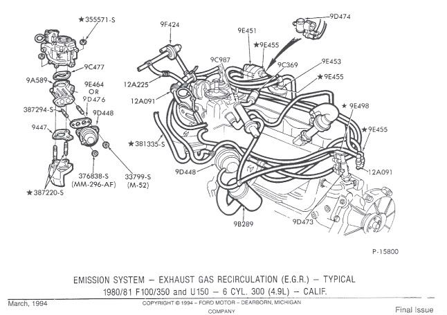
scan0050.jpg


Need a closer look?

click this 4 times


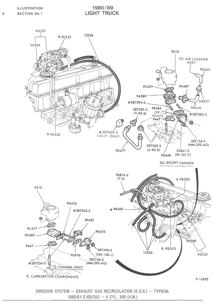
This version below is for E-series

scan0052.jpg
 
Last edited:
YES...there it is! Great drawings Mil1ion. It shows the VCV's and the hose I'm missing on the back side..and a breakout of the thingy I'm missing on the driver side up by the valve cover, 9D474.

I think you put me over the top.

With all the diagrams you sent along and this last set make it all start to make sense.

Some other lost soul with a Ca. '80 4.9 will benefit as well.

Thanks you sir,
Dave
 
Last edited:

BKW

Ford Parts Guru
The carb originally had a tri-angular shaped tag bolted to the airhorn I was told. It would be rare for a tag to survive 30 years I suppose.

Could it be that the number on the tag would have been the Ford part number? Absolutly not! I would bet on that. :rofl: You'd lose!
There are no actual Ford part numbers marked on any parts after 1956. Only casting and ID Engineering numbers are present (when applicable).

Casting numbers cannot be cross referenced to Ford part numbers, ID Engineering numbers can. Numbers marked on carb bases are ID Engineering numbers.

Most people haven't a single clue when Ford numbers are present...don't know a part number from a casting or ID Engineering number. I see this jazz everyday on websites, ebay and etc.

But most Ford partsguys know, cuz they've been subjected to this jazz 1000's of times.

Originally typed in post #24: Carb ID tag number: E0TE-ALA / Ford part number: E0TZ-9510-AL (Motorcraft CA2287).

E0TZ-12A091-A .. VCV Valve (Motorcraft DY271) / Marked with ID Engineering number: D8AE-BA

And, btw: There is no 9D474 = EGR Solenoid Vacuum Valve listed in either Calibration Code parts list for your trucks application. So, it's not missing, cuz it wasn't there to begin with.

While parts catalog illustrations can be used as an assembly manual, keep in mind that these are TYPICAL illustrations only...and are used by partsguys to find the basic part numbers.

Just because basic part numbers are illustrated, doesn't mean that all vehicles actually used them. It all depends on the specific vehicles application.
 
Last edited:
Bill is correct Dave

I tried for the EXACT routing diagram with the exact Calibration Code so I could scan the Parts list for the application you needed

Unfortunately or Fortunately depending on how you look at it Hose routing illustrations like the green one above I don't have beyond 1978. In 1979 aside from the P & I books book that Bill and I have those renderings are generic so I posted it just for something closer to go off of.

Since I can't find an 1980 book for schematics and noticed that some in 1981 continue on from 1977 Bill and I were able to only get you so close.
The best thing for you is studying the sticker schematic that you posted.

The reason why is that because there are close to 22 different calibration codes for each year ,1979-1981 It is back to you to understand and apply your sticker Vacuum Map

Here is what I was trying to find you for your truck.This one is for 6.6L from my 1982 emission book but the CC was original from 1979.


Glad I could and feel free to plaster my user name on the other site in the 73-79 letting people know how helpful Numberdummy and Mil1ion were over at a different Ford site since they teamed up :)

If I come across anything more for your year, I'll post it here.

Zoom Zoom !
 
Last edited:
Thanks for all of the above Bill. I'm glad that that solenoid is not correct. I'm not betting with you anymore ;-)

I am just going by the diagram now. I guess the diagram location of the second VCV shown by the distributor is approximate and that both are supposed to be together up front like mine are. I wonder why they bothered to put Front of Engine at the left margin of the routing diagram if they did not draw components where they actually are... both the VCV symbols, according to the Ford parts guy are thermostatic and need to be in the cooling system loop, not hanging out by the distributior.

There is one abbreviation, or is it acronym, that has me a little puzzled.
The sticker shows INT MAN going up to the A/CL BI-MET and on to the A/CL DV. It also requires that INT MAN go up to the second VCV off of the thermostat housing. I am guessing INT MAN is the same as MAN VAC.
I have 3 lists shorthand Fordese and INT MAN does not appear.

The only thing besides hose I need to find is the DV-TW gizmo and the V REST that goes in the line from INT MAN to the 2nd VCV.

Thanks again for all the help Bill. I'm taking pics as I go and I am going to stick them in my Gallery. Maybe they will prevent another Ca. lost soul from asking a bunch of dumb questions and making it harder than it ought to be.

Dave
 
Most of these parts can be had off cars as well and are also available new.

I don't use any of those emissions things on my pre 88-vehicles so I have some used parts for these guys.
 

BKW

Ford Parts Guru
DaveMorgan said:
I guess the diagram location of the second [confused] VCV...
Look to the far right in this pic...notice the arrow pointing to 12A091.

Now look below and just to the left...notice the arrow pointing to 9D473.

This 12A091 is the VCV, there is only one! / The other 12A091 (rear of engine) is a vacuum delay valve. It's plastic, round with a nipple on either side, tu-tone color coded and has an ID number molded into the plastic.

There are two of the following:

1) D3TZ-9D473-A .. EGR Vacuum Control Valve Assy / Marked: D7ZE-A1A or -B2A.

1) D8TZ-9D473-B .. EGR Vacuum Control Valve Assy (Motorcraft CX 241-A) / Marked: D8TE-B1A or -B2A.

One of these valves threads into the t/stat housing, t'other into the location shown in the pic.
 
Last edited:

BKW

Ford Parts Guru
I rep'd you for the above info...take a look and see what I typed. Knowing you, :rotz: I'll betcha it's accurate!
 
You guys are good! No quit in either of you. This pic will probably explain why I'm hung up on VCV's and where they are located. Here is my setup. Not correct, if I'm not mistaken right?
002-1.jpg


I suppose the one on the left is correct and the one on the right is a workaround a PO added. Those two items are what have had me chasing my tail. I could not get past them without creating even more confusion.

What now guys? punt?

Thanks,
Dave
 
Those parts are designed to fit properly.

My best explanation of that pic

The hose that comes across the top to the VCV on the right..is INCORRECT

Remove it.

There should be a double nipple connector with a vacuum hose attached that slides into the two rubber receiver connector.

That plastic connector at that spot should look like this

Item 57-5116

on this page

http://www.myvirtualpaper.com/doc/carquest/carquest-engine-controls-catalog/2010111901/379.html#1360


Someone has really Batardized the vauum hoses.

Can you draw a schematic of where all the hoses attached to the VCV on the right go ?
 
Last edited:

BKW

Ford Parts Guru
You guys are good! No quit in either of you. This pic will probably explain why I'm hung up on VCV's and where they are located. Here is my setup. Not correct, if I'm not mistaken right?
002-1.jpg


I suppose the one on the left is correct and the one on the right is a workaround a PO added.
Look on both of these valves for their ID numbers, post what they are.

The numbers are molded into the plastic housing on a raised oblong platform.

These numbers are a necessity, for without them...there is no way = none...we can tell you if one or both are correct...or not...for the application.
 
Mil1ion and BKW,

Here is the best pic I could get of the numbers on the four nipple valve on the left: With my cheaters on and a magnifying glass it reads: V28 3180 There are letters near each of the four ports, and reading from the bottom up they are: S, E, M, D. The hoses incoming/outgoing are run according to the diagram. Something is not right though because there is no vacuum at operating temp at any rpm level. Bad switch?

http://i900.photobucket.com/albums/ac205/camoclown/002-2.jpg

The valve on the right has no numbers. There is a good sized flat area where you said to expect them, but no joy. It does have numbers/letters for each port. Reading from the bottom I see 2, D, 1..or I

http://i900.photobucket.com/albums/ac205/camoclown/001-1.jpg

The bottom port, still routed the way I found it, goes to MAN VAC. The next port up goes to the distributor. The loop shunt shown in the earlier pic went to the top port of the 4 port switch on the left...don't know why the PO had it there. The shunt is removed and both top ports are capped for now.

This switch provides no vacuum to the ports above the MAN VAC incoming port at operating temperature. I can pull the distributor vac line at operating temp and at any rpm above idle and it no suckee. The MAN VAC incoming at the bottom sucks like a leech. As a matter of fact this whole nest of vacuum lines sucks ;-) The diagram shows a single VCV up front and another valve over by the distributor....not two side by side.
Is the diagram always correct? How did it pass the smog visual for the PO if the second valve is out of place, doesn't work, and probably rigged wrong....

The strange part is the truck runs fine. Runs cool too. It is a smelly bugger though. It would not pass smog the way it is now. Compression is 150 on all 6 and the carb is running lean. Blowby is minimal. I timed it up by vacuum to 18 and dialed it back to 17 and sitting now at 12 BTDC.

New carb, new head, new iginition stuff, new EGR, new fuel, no intake leaks...

Oh well....I will go stare at the diagram again for awhile.

Dave
 
The VCV that shows near the distributor on the diagram doesn't necessarily mean it mounts near the dist.
It is only there to show the routing of hoses.
You will also notice that one of those ports is CAPPED on that VCV

003-1.jpg


Looks likes it is time for me to start scanning and posting what operation certain parts do and how to test them.
 
Last edited:

Ford Truck Articles

Top