Join Our Ford Truck Forum Today

Document your Ford truck project here and inspire others! Login/Register to view the site with fewer ads.

Fan Circuit Bug

Skandocious

Post Whores Make Me Sick
19,076
655
California
One other major problem your circuit has, the temp sensor will supply the current for the AC compressor clutch winding. It is not designed for that much current.
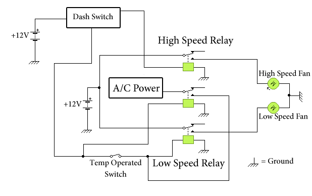
You're correct. But I didn't design it to do that, that's by accident. Can't I just put a diode on that wire to prevent it from supplying current to the compressor? That's the point of this whole thread-- it is backfeeding power to my compressor and I don't want it to.
 
I'm not sure I understand what you mean by all this...
Back when I used to live out in California, I had to make numerous trips over the grapevine weekly. I was driving a POS that will remain nameless, but it had an electric 2 speed fan. Low when the AC was on and HI when full-on cooling was needed.
Making the pull on that grade during the summers generally meant that I had to get all the cooling I could out of it. I mounted a 3 position dual-pole rocker switch and wired it straight to the thermostat/sensor on the radiator. up, it acted like the thermostat was turning it on. center was normal operation and down I used to cut power to the fan altogether for winter warmups and defrost mode. to avoid power conflicts with the AC/lo side while I had the fan in HI mode, I wired in a relay that broke the connection on the LO side when I powered on the Hi side. I considered a barrier diode, but just couldn't get myself to trust it.
Hope that makes it as clear as mud... anyway thanks for reading
 

radialarm

Clown of Death!
newfancircuitwithlabels2.png


Well I got in a hurry, but with 5 pin relays mine would work!!!

If you put the diode where I indicated it will stop the backfeed!!!
 

Skandocious

Post Whores Make Me Sick
19,076
655
California
Well I got in a hurry, but with 5 pin relays mine would work!!!
Robert your circuit would work but it would allow power to both windings in the fan at once. I'm already using 5 pin relays for the smaller ones. The larger 75amp relay for the high speed is only a 4 pin because that's all I could find (and trust me I SEARCHED).

radialarm said:
If you put the diode where I indicated it will stop the backfeed!!!
This is what I've been talking about all along. I just don't know if it's the right thing to do.
 

radialarm

Clown of Death!
Robert your circuit would work but it would allow power to both windings in the fan at once. I'm already using 5 pin relays for the smaller ones. The larger 75amp relay for the high speed is only a 4 pin because that's all I could find (and trust me I SEARCHED).

This is what I've been talking about all along. I just don't know if it's the right thing to do.
Everything else is fine just that one little defect. The complications in this situation are one reason I used 5 relays!!!
 

Skandocious

Post Whores Make Me Sick
19,076
655
California
Everything else is fine just that one little defect. The complications in this situation are one reason I used 5 relays!!!
It's a big defect Robert. Can cause damage to the fan motor if both windings get power. That is the number 1 issue that I was having when I was designing circuit after circuit after circuit... :headbang:

But look out because I figured it out!!! I had it all wrong! I was using the inductive circuit on the A/C relay when I should have just been using the relay to bypass the temp switch! Observe!


circuit2.png


The A/C circuit is only ever touching the inductive circuit on that relay, so there is no way for the power to backfeed back to the A/C circuit. It's totally isolated from the fan circuit!!! WOO!
 

radialarm

Clown of Death!
You could add one more relay like this, but I cant see how putting a diode in the place I indicated would cause any problems!!!

ChrisFan2.jpg
 

radialarm

Clown of Death!
It's a big defect Robert. Can cause damage to the fan motor if both windings get power. That is the number 1 issue that I was having when I was designing circuit after circuit after circuit... :headbang:

But look out because I figured it out!!! I had it all wrong! I was using the inductive circuit on the A/C relay when I should have just been using the relay to bypass the temp switch! Observe!


circuit2.png


The A/C circuit is only ever touching the inductive circuit on that relay, so there is no way for the power to backfeed back to the A/C circuit. It's totally isolated from the fan circuit!!! WOO!
That will do it!!!
 

Skandocious

Post Whores Make Me Sick
19,076
655
California
So going back to my currently wired circuit... In order to change it to the new one, it appears to me that I'd just have to swap the 30 and 85 pins on my A/C relay, right?


Old:

newfancircuitwithlabels.png


New:

circuit2.png
 

Skandocious

Post Whores Make Me Sick
19,076
655
California
No takers? I'm gonna try and fix this here in a few minutes. Best I can tell I just need to swap those two terminals...
 
OK, so how about a conclusive daigram, splainin' what you did, and PIX?
 

Skandocious

Post Whores Make Me Sick
19,076
655
California
This is the conclusive diagram of exactly how it's wired in my truck right now:


circuit2.png


All I had to do was swap the 30 and 85 pins on my A/C relay (in the diagram, the two pins on the left side of the relay) in order to put the A/C compressor wire onto the INDUCTIVE circuit of the relay. This isolated it from the switched circuit and therefore prevented the possibility for backfeeding from ever occurring :D

Pix? Nahhh. Too embarrassed to post pictures of my twisted mess of wires. I've rewired it so many times that it just looks HORRID. The wiring diagram should tell you everything you need to know :D
 
Last edited:

john112deere

caffeine junkie
Staff member
10,807
405
central Vermont
Forgive me for not bein' too swift when it comes to electrical stuff.

What causes the fan to go on "high" when it's in automatic mode?
 

Skandocious

Post Whores Make Me Sick
19,076
655
California
Forgive me for not bein' too swift when it comes to electrical stuff.

What causes the fan to go on "high" when it's in automatic mode?
Nothing. Ever :p I only want to high speed to be activated by MANUALLY switching the switch on the dash. It pulls too many amps for me to ever be comfortable with running it on a daily basis. The only times I've ever had to use it included the snow trip, towing the boat, and a little during the pismo trip. And even during those times I only used it off and on to make sure my trans stayed cool enough-- the low speed is capable of cooling my engine no matter what.
 

john112deere

caffeine junkie
Staff member
10,807
405
central Vermont
Oh.

The fact that there IS a high-speed, suggests to me that in the car the fan was original-equipment in (Taurus?) would engage the high-speed setting under certain conditions. Any idea what triggered it in that car?

*Reason I ask, is I'm now the owner of a Ford with a factory e-fan. It works fine, but I'm curious how it works.
 

Skandocious

Post Whores Make Me Sick
19,076
655
California
I'm not familiar with the circuitry in the T-bird that this fan came from, but my assumption has always been that it had more complicated/advanced circuitry, most likely computer controlled, that could either ramp the fan speed gradually between low speed and high speed, or disable the low speed and enable the high speed when the engine reached extreme temperatures. I find it hard to believe that the t-bird, being a small car with a V6 engine, would have problem staying cool with the low speed when my truck stays cool just fine, except under extreme conditions.

So I guess the short answer is that I don't have a good answer for you. I'm not sure how the high speed is used in the t-bird. I do know that the t-birds and taurus' that were equipped with these high powered fans also all run 130amp alternators. Geez that's an awful powerful alternator for such a small car. Coincidence? I think not ;)
 

Ford Truck Articles

Recent Forum Posts

Top