Skandocious
Post Whores Make Me Sick
Here is a real quick writeup for installing a toggle switch for the torque converter clutch on E4OD-equipped trucks.
DISCLAIMER: Use of a manual control TCC lockup switch, as described in the following writeup, can cause your transmission to entire limp mode if used excessively. Transmission damage should not result, and the condition can be remedied by simply resetting the computer. Generally problem will occur if one keeps the TCC unlocked for an extended period of time when the computer is expecting it to be locked (eg, extended drives at freeway speeds). Again -- this mod should not harm your transmission in any way, but be aware that the computer will sometimes have a temper tantrum for not having control of the TCC
Materials you'll need:
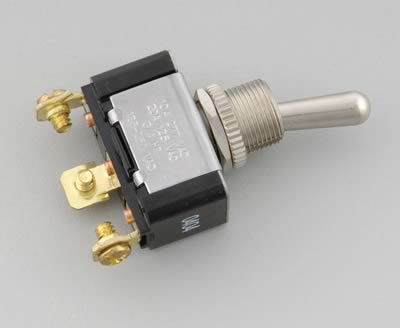
*3-position (on/off/on) switch
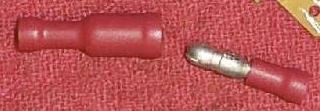
*4 "bullet disconnect" electrical crimp connectors (2 male, 2 female)
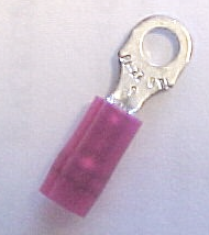
*3 small ring terminal crimp connectors (small enough to fit the screws on that 3-position switch terminals, but large enough to accommodate the gauge of wire you're using in the crimp)
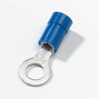
*1 medium sized ring terminal connector (large enough to fit around the grounding bolt under the driver-side kick panel --- my guess is that the inner diameter of the ring connector should be roughly 1/8 - 1/4". Just eyeball the size and buy a ring connector accordingly)
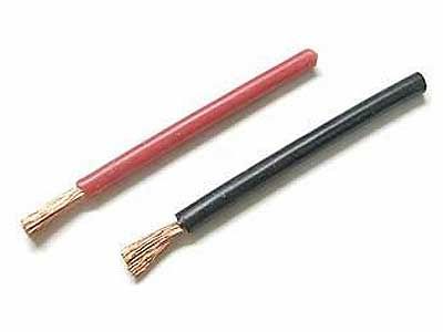
*10-15 feet of wire (your choice on size -- I used 14 AWG because I have a HUGE spool of it) [note: make sure that you buy wire that matches your crimp connector size] [note2: I recommend getting 3 equal lengths of DIFFERENT colored wire -- for example: 5 feet red, 5 feet black, and 5 feet green --- this will make it easier when wiring your switch]
[note: it's always a good idea to buy extra crimp connectors and extra wire -- I always screw up on at least one of my crimps and have to redo it]
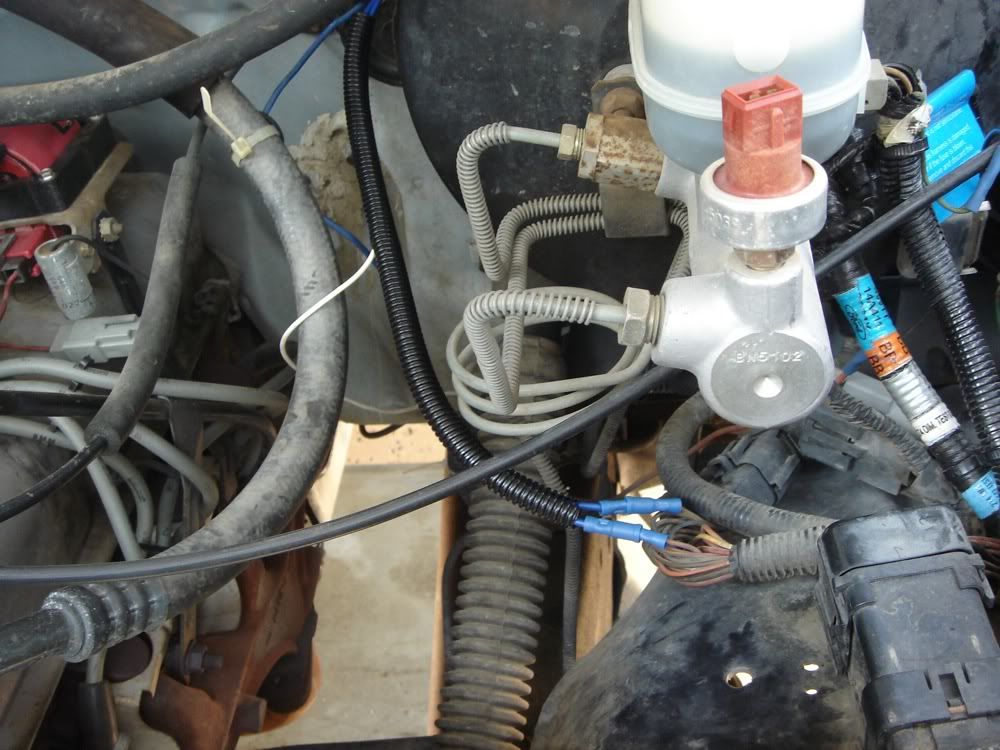
Step 1: Locate the transmission harness which is mounted on the driverside fender-well of most Gen 8-9 pickup trucks. If you can't figure out which is the right one, get under the truck and trace the wire spool coming from the passenger side of the transmission -> up and over the trans -> up the frame rail towards the engine -> and then up into the engine compartment. Once you have located the harness, you need to locate to the PURPLE/YELLOW wire in the harness. That is, the PURPLE wire with a YELLOW tracer on it.
Step 2: Snip the wire, leaving ample slack on both sides of the cut to strip the insulation and crimp on your connectors.
Step 3: You guessed it --- strip the insulation off. NOT TOO MUCH! You only need a few millimeters of bare wire to crimp, so that you don't leave exposed wire outside of the connector (shorting hazard). To get an idea of how much exposed wire you need, look at the electrical connector your using and look at the crimping section of the connector --- thats roughly how much you should strip away.
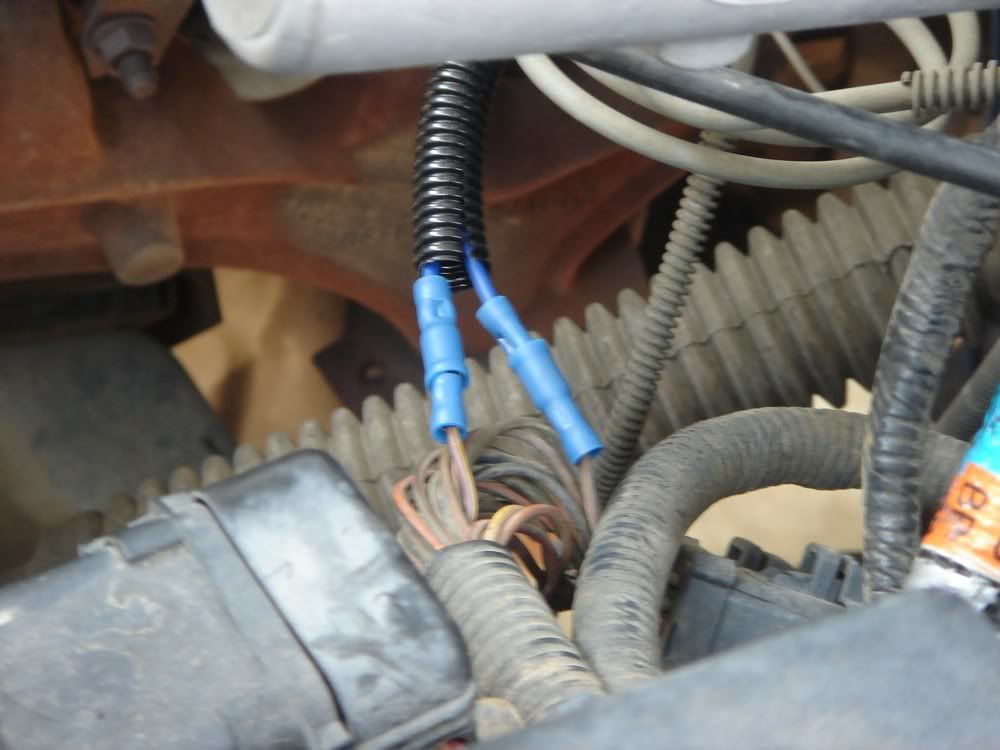
Step 3: Crimp a MALE connector onto 1 of the exposed purple/yellow wires and crimp a FEMALE connector onto the other. We want opposing connectors here so that if we ever want to UNDO this mod we can just plug these two back together and return to stock.
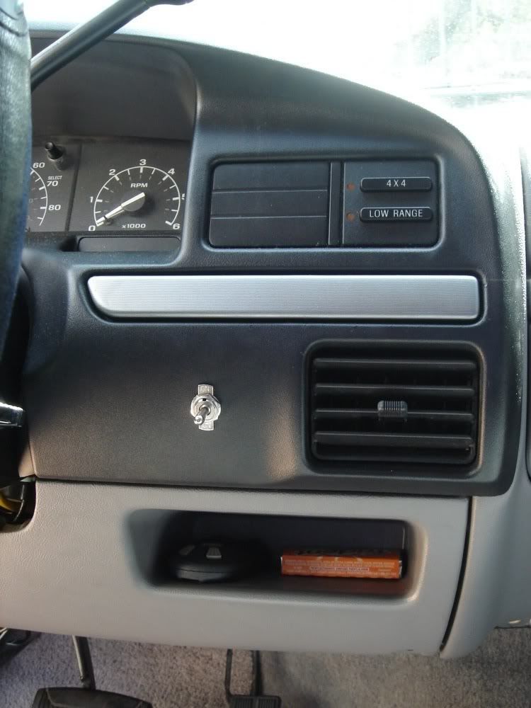
Step 4: This step is going to require a bit of your OWN thinking (oh no!!) You're going to want to locate the switch at the blank part of your dash where you plan on installing it, then you'll need to eyeball the amount of wire that will be required to take a piece of wire from the switch, through the firewall, and into the engine compartment where you can connect it to the bullet disconnects that we just crimped. I located mine to the right of the steering column and I believe it took 3-4 feet of wire to get it into the engine compartment. Alternatively, you can drill the hole for the switch and install it, then run an excess amount of wire from the switch into the engine compartment (or vice versa) and cut it when it reaches the proper distance. You will need TWO pieces of wire cut to the proper length. Again --- this step can be performed however you like, just use common sense. If you have no common sense, place the truck in reverse and lay down behind the front tire
Step 5: Take your first piece of wire, strip the insulation from the ends and crimp a FEMALE bullet connector to one end, and a ring terminal connector at the other.
Step 6: Take your second piece of wire, strip the insulation from the ends and crimp a MALE bullet connector to one end, and a ring terminal connector at the other.
Step 7: Connect the bullet connectors on the wires to the opposing connectors on the purple/yellow wire in the engine compartment. Then run both wires through the firewall and up to where your switch will be located.
Step 8: Cut a length of wire that is long enough to reach from your switch location to the lower portion of the driver-side kick panel. On this wire you will crimp your third small ring terminal connector at one end and your medium ring terminal connector at the other end.
Step 9: Remove the driver-side kick panel to expose the green-colored grounding bolt located below the hood release lever. Unscrew the grounding bolt and slide your medium ring terminal connector around the threaded side of the bolt, then screw it tightly back in place. Route the wire up to your switch and replace kick panel.
Step 10: You should now have 3 small ring terminal connectors near where your switch will be located -- two from the engine compartment and 1 from the grounding bolt. Remove the 3 screws from terminals on the 3-position switch, and screw the grounding bolt terminal to the TOP terminal on the switch (refer to the ON stamps on the front of the switch to figure out which one is top and which is bottom).
Step 11: Take the wire that is coming from the COMPUTER side of the purple/yellow and connect it to the BOTTOM terminal on the back of the switch.
Step 12: Lastly, take the wire coming form the TRANSMISSION side of the purple/yellow and connect it to the MIDDLE terminal on the back of the switch.
If wired correctly, it should look like this:
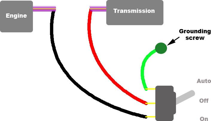
Explanation of how this works... The torque converter clutch is LOCKED when the purple/yellow wire going to the transmissions gets grounded. All the switch is doing is choosing when the transmission is going to get ground. Here is what the internals of the 3 position switch look like:
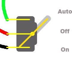
Position1:
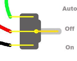
Position 2:
Position 3:
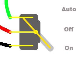
As you can see... We're taking either the computer signal from the bottom post, or the ground from the top post, and just redirecting that charge onto the center post -- which goes out to the transmission.
You'll notice that because of the nature of the switch, the top and bottom posts are swapped from what common sense tells you they SHOULD be. The upper position of the switch corresponds to the computer controlling the TCC, and yet the upper POST on the back of the switch is connected to ground. This is because inside the switch is just a solid bar that redirects power, as you can see in my diagrams above.
So thats it for my tech writeup!
DISCLAIMER: Use of a manual control TCC lockup switch, as described in the following writeup, can cause your transmission to entire limp mode if used excessively. Transmission damage should not result, and the condition can be remedied by simply resetting the computer. Generally problem will occur if one keeps the TCC unlocked for an extended period of time when the computer is expecting it to be locked (eg, extended drives at freeway speeds). Again -- this mod should not harm your transmission in any way, but be aware that the computer will sometimes have a temper tantrum for not having control of the TCC
Materials you'll need:
*3-position (on/off/on) switch
*4 "bullet disconnect" electrical crimp connectors (2 male, 2 female)
*3 small ring terminal crimp connectors (small enough to fit the screws on that 3-position switch terminals, but large enough to accommodate the gauge of wire you're using in the crimp)
*1 medium sized ring terminal connector (large enough to fit around the grounding bolt under the driver-side kick panel --- my guess is that the inner diameter of the ring connector should be roughly 1/8 - 1/4". Just eyeball the size and buy a ring connector accordingly)
*10-15 feet of wire (your choice on size -- I used 14 AWG because I have a HUGE spool of it) [note: make sure that you buy wire that matches your crimp connector size] [note2: I recommend getting 3 equal lengths of DIFFERENT colored wire -- for example: 5 feet red, 5 feet black, and 5 feet green --- this will make it easier when wiring your switch]
[note: it's always a good idea to buy extra crimp connectors and extra wire -- I always screw up on at least one of my crimps and have to redo it]
Step 1: Locate the transmission harness which is mounted on the driverside fender-well of most Gen 8-9 pickup trucks. If you can't figure out which is the right one, get under the truck and trace the wire spool coming from the passenger side of the transmission -> up and over the trans -> up the frame rail towards the engine -> and then up into the engine compartment. Once you have located the harness, you need to locate to the PURPLE/YELLOW wire in the harness. That is, the PURPLE wire with a YELLOW tracer on it.
Step 2: Snip the wire, leaving ample slack on both sides of the cut to strip the insulation and crimp on your connectors.
Step 3: You guessed it --- strip the insulation off. NOT TOO MUCH! You only need a few millimeters of bare wire to crimp, so that you don't leave exposed wire outside of the connector (shorting hazard). To get an idea of how much exposed wire you need, look at the electrical connector your using and look at the crimping section of the connector --- thats roughly how much you should strip away.
Step 3: Crimp a MALE connector onto 1 of the exposed purple/yellow wires and crimp a FEMALE connector onto the other. We want opposing connectors here so that if we ever want to UNDO this mod we can just plug these two back together and return to stock.
Step 4: This step is going to require a bit of your OWN thinking (oh no!!) You're going to want to locate the switch at the blank part of your dash where you plan on installing it, then you'll need to eyeball the amount of wire that will be required to take a piece of wire from the switch, through the firewall, and into the engine compartment where you can connect it to the bullet disconnects that we just crimped. I located mine to the right of the steering column and I believe it took 3-4 feet of wire to get it into the engine compartment. Alternatively, you can drill the hole for the switch and install it, then run an excess amount of wire from the switch into the engine compartment (or vice versa) and cut it when it reaches the proper distance. You will need TWO pieces of wire cut to the proper length. Again --- this step can be performed however you like, just use common sense. If you have no common sense, place the truck in reverse and lay down behind the front tire
Step 5: Take your first piece of wire, strip the insulation from the ends and crimp a FEMALE bullet connector to one end, and a ring terminal connector at the other.
Step 6: Take your second piece of wire, strip the insulation from the ends and crimp a MALE bullet connector to one end, and a ring terminal connector at the other.
Step 7: Connect the bullet connectors on the wires to the opposing connectors on the purple/yellow wire in the engine compartment. Then run both wires through the firewall and up to where your switch will be located.
Step 8: Cut a length of wire that is long enough to reach from your switch location to the lower portion of the driver-side kick panel. On this wire you will crimp your third small ring terminal connector at one end and your medium ring terminal connector at the other end.
Step 9: Remove the driver-side kick panel to expose the green-colored grounding bolt located below the hood release lever. Unscrew the grounding bolt and slide your medium ring terminal connector around the threaded side of the bolt, then screw it tightly back in place. Route the wire up to your switch and replace kick panel.
Step 10: You should now have 3 small ring terminal connectors near where your switch will be located -- two from the engine compartment and 1 from the grounding bolt. Remove the 3 screws from terminals on the 3-position switch, and screw the grounding bolt terminal to the TOP terminal on the switch (refer to the ON stamps on the front of the switch to figure out which one is top and which is bottom).
Step 11: Take the wire that is coming from the COMPUTER side of the purple/yellow and connect it to the BOTTOM terminal on the back of the switch.
Step 12: Lastly, take the wire coming form the TRANSMISSION side of the purple/yellow and connect it to the MIDDLE terminal on the back of the switch.
If wired correctly, it should look like this:
Explanation of how this works... The torque converter clutch is LOCKED when the purple/yellow wire going to the transmissions gets grounded. All the switch is doing is choosing when the transmission is going to get ground. Here is what the internals of the 3 position switch look like:
Position1:
Position 2:
Position 3:
As you can see... We're taking either the computer signal from the bottom post, or the ground from the top post, and just redirecting that charge onto the center post -- which goes out to the transmission.
You'll notice that because of the nature of the switch, the top and bottom posts are swapped from what common sense tells you they SHOULD be. The upper position of the switch corresponds to the computer controlling the TCC, and yet the upper POST on the back of the switch is connected to ground. This is because inside the switch is just a solid bar that redirects power, as you can see in my diagrams above.
So thats it for my tech writeup!
")