Join Our Ford Truck Forum Today

Document your Ford truck project here and inspire others! Login/Register to view the site with fewer ads.

Rough Running OBD 2195 and 2197

'05 E350 V10 Torqshift.
I'm getting codes 2195 and 2197 and the engine is running very rough. Can someone tell me what these codes mean and what it's likely to cost to get it fixed?
 

blacksnapon

Moderator
Staff member
H16 DTCS P0171, P0174, P1130, P1131, P1150, P1151, P2195 OR P2197: LEAN SYSTEM DTCS
Note: Do not clear the DTCs or reset the keep alive memory (KAM).

Access the PCM and record the ECT PID from the freeze frame data. The freeze frame data is used to recreate the concern.
Retrieve and record the self-test DTCs.
Are any DTCs present other than the following: P0171, P0174, P1130, P1131, P1150, P1151, P2195 or P2197?
Yes No
DISREGARD the current diagnostic trouble code (DTC) at this time. DIAGNOSE the next DTC. GO to Section 4, Diagnostic Trouble Code (DTC) Charts and Descriptions. GO to H17 .

H17 CARRY OUT A VISUAL INSPECTION ON THE INTAKE AIR SYSTEM AND ALL VACUUM HOSES
Check the intake air system for leaks, obstructions, and damage.
Inspect the entire length of all the vacuum hoses for:
proper connections
damage or cracks
damaged or cracked vacuum tees
Verify the integrity of the positive crankcase ventilation (PCV) system.
Verify the proper PCV valve part number.
Is a concern present?
Yes No
GO to H20 . GO to H18 .

H18 CHECK FOR THE PRESENCE OF A VACUUM LEAK
Note: Fuel trim values at idle are more sensitive to a vacuum leak. The vacuum leak (unmetered air) represents a larger portion of the total air flow at idle than at part throttle.

Note: The barometric pressure (BARO) PID is not a recommended PID to monitor when diagnosing a vacuum leak. Barometric pressure is calculated during high engine load, when the vacuum leak represents a small portion of the total air flow.

Note: When calculating the total fuel correction in the following steps, if LONGFT1 equals +13% and SHRTFT1 equals +23%, the total fuel correction for bank 1 equals +36%. If LONGFT2 equals +24% and SHRTFT2 equals -3% the total fuel correction for bank 2 equals +21%.

Note: If the freeze frame ECT PID is available, stabilize the engine at the temperature recorded by the freeze frame ECT PID. If the freeze frame ECT PID is not available, maintain the engine coolant temperature between 82°C - 101°C (180°F - 215°F) and the intake air temperature less than 46°C (115°F).

Key ON, engine running.
Access the PCM and monitor the ECT, CHT and IAT PIDs.
Access the PCM and monitor the LONGFT1, SHRTFT1, LONGFT2 and SHRTFT2 PIDs.
Allow the engine to stabilize at the temperature necessary to recreate the concern.
Mathematically add and record the LONGFT PID value to the SHRTFT PID value for each bank, for a total fuel correction at idle.
Increase the engine speed to 3,500 RPM for 10 seconds. For vehicles with electronic throttle control (ETC), increase the engine speed to the maximum RPM without activating RPM limiting.
Record the LONGFT1, SHRTFT1, LONGFT2, and SHRTFT2 PID values.
Mathematically add and record the LONGFT PID value to the SHRTFT PID value for each bank, for a total fuel correction at 3,500 RPM or the maximum allowable RPM for vehicles with ETC.
Is the total fuel correction value difference, between idle and 3,500 RPM or the maximum allowable RPM for vehicles with ETC, less than 15 percent?
Yes No
No vacuum leak is present.

GO to H22 . GO to H19 .

H19 LOCATE THE VACUUM LEAK
CAUTION: Do not clamp or pinch a hard plastic hose. Use a vacuum cap or equivalent to restrict the hose.

Note: Restricting the EVAP vapor hose while the EVAP emission canister is purging may shift the SHRTFT. Carry out a visual inspection as necessary.

Note: When monitoring for a decrease in the SHRTFT PIDs in the following steps, if SHRTFT1 equals +15% and the hose is restricted, SHRTFT1 decreases to -7%. The total decrease in the SHRTFT PIDs equals 22%.

Locate the vacuum tees for the intake air and PCV systems.
Access the PCM and monitor the SHRTFT1 and SHRTFT2 PIDs.
Restrict the vacuum lines one at a time for 30 seconds. If a vacuum leak is present, the SHRTFT PID values will decrease as the hose is restricted.
Is the decrease in the SHRTFT PIDs greater than 15 percent when one of the vacuum hoses is restricted?
Yes No
GO to H20 . INSPECT the intake air system for a vacuum leak in the intake manifold or intake gaskets. REPAIR as necessary.

For repair verification, GO to H20 .

H20 VACUUM LEAK REPAIR VERIFICATION
Note: If the freeze frame ECT PID is available, stabilize the engine at the temperature recorded by the freeze frame ECT PID. If the freeze frame ECT PID is not available, maintain the engine coolant temperature between 82°C - 101°C (180°F - 215°F) and the intake air temperature less than 46°C (115°F).

Access the PCM and monitor the SHRTFT1 and SHRTFT2 PIDs.
Allow the engine to stabilize at the temperature necessary to recreate the concern.
Record the SHRTFT1 and SHRTFT2 PID values.
Key in OFF position.
Repair the vacuum leak.
Key ON, engine running.
Allow the engine to stabilize at the temperature necessary to recreate the concern.
Access the PCM and monitor the SHRTFT1 and SHRTFT2 PIDs.
Compare the recorded SHRTFT PID values, prior to the vacuum leak repair, to the current SHRTFT PID values.
Is the decrease in the SHRTFT PIDs greater than 15 percent?
Yes No
Fault found.

RESET the keep alive memory (KAM). REFER to Section 2, Resetting The Keep Alive Memory (KAM). A vacuum leak is still present,

GO to H19 .
 
Thanks for the relpies.

Took the cover off the motor inside the van to look for anything unusual.
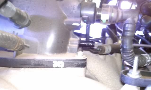
The first thing I noticed was that there isn't anything connected to this port (black nipple). Should it be connected to something or plugged?
IMAG0356.jpg


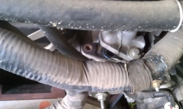
Then I got to following some of the vacuum lines and noticed this.
IMAG0353.jpg


It's a half open port of some kind on the very end of the motor on the passenger side, even equipped with an "O" ring?
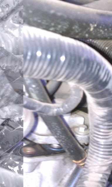
IMAG0354.jpg


It sure doesn't look like there's really any room for anything to be connected there?

Would I be able to find a vacuum leak if I started the motor and listened around?
 
When I block that black nipple, I get my regular idle back, but I've since noticed that the a/c only blows air to the defroster. Is that port supposed to supply vacuum to the heat and air control system? If so where would I find the other end of that hose?

Or did I just screw something else up while I was messing around?
 

smokey

Hitech hillbilly
Staff member
I'm not real familiar with the v10 or the E series but there should be something on that nipple. I would guess a line fell off some one else may know the vacuum diagram for this engine. My guess it ties in to the climate controllers.
That open port I haven't a clue why it is that way.
 

Ford Truck Articles

Recent Forum Posts

Top